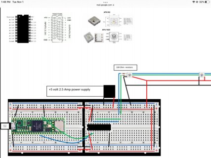
Anyone mind doing a quick look over my schematic
Basically showing a teensy 4.1 thats connected to a computer through a micro usb, thats feeding SPI (data and clock signals) to a level shifter (3.3v to 5v) which sends those translated signals to my RGBLED’s. The led’s need 5 volts, and the teensy is only capable of 3.3 volts so an external power supply is powering the led’s.
I mostly just need to know if the grounds are in the right place, particularly the ones connected to the microcontroller.