Hi all,
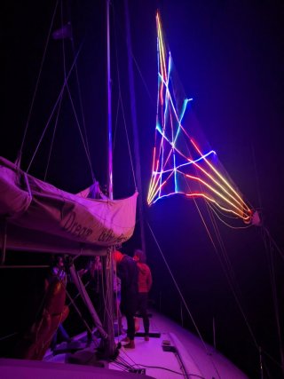
I'm working on the expansion of a project that I have coined disco jib which has been created for a private music festival and to bring some LED art to sailing trips. In its current configuration the disco sail utilizes two OctoWS2811 and FastLED library to control a total of 12 individual 5m RGB LED strips (1x 8 strips and 1x 4 strips). There is either a preprogrammed light show or the possibility to change effects via Serial interface and a Python script running on a laptop. Please find attached a picture of the installation during a recent sailing trip.
For the next version of the disco jib I want to implement DMX control of the entire installation.
Software used:
- The freeware QLC+ for DMX control and light shows (https://www.qlcplus.org/)
- TeensyDMX library (https://github.com/ssilverman/TeensyDMX)
Additional hardware for DMX upgrade:
- a USB to DMX RS485 adapter with FTDI chip for connection to the OctoWS2811's (https://www.amazon.de/dp/B07WV6P5W6?ref_=pe_27091401_487187591_302_E_DDE_dt_1)
- a UART TTL to RS485 adapter 485 Seriell 3.3V/5V (https://www.ebay.de/itm/153880466847)
- a female 3pin DMX socket
I ran into troubles making the DMX connection work and despite quite some time invested cannot find the problem.
This is the script I'm trying on the Teensy (from here: https://forum.pjrc.com/threads/66083-Receiving-DMX-with-a-RS-485-and-Teesny-4-1):
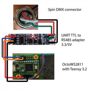
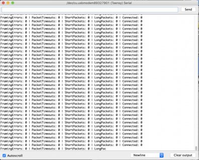
Attached you can find the wiring. The script does not seem to receive any DMX signals. dmxRx.connected() is returned with false and no errors are reported (see screenshot). The DMX input via QLC+ itself is confirmed to be working as it should with a separate DMX-controlled light. The RS485 board has been successfully used with an Arduino Uno and the DMXSerial library.
Anyone has an idea what might be wrong? I'm concerned the type of RS485 module I am using might be the problem as I cannot switch it manually to "receive" mode but it switches automatically (see here: https://electronics.stackexchange.com/questions/244425/how-is-this-rs485-module-working). It may be in the wrong mode for the TeensyDMX library to work properly?
Any help would be highly appreciated.
Thanks a lot!
I'm working on the expansion of a project that I have coined disco jib which has been created for a private music festival and to bring some LED art to sailing trips. In its current configuration the disco sail utilizes two OctoWS2811 and FastLED library to control a total of 12 individual 5m RGB LED strips (1x 8 strips and 1x 4 strips). There is either a preprogrammed light show or the possibility to change effects via Serial interface and a Python script running on a laptop. Please find attached a picture of the installation during a recent sailing trip.
For the next version of the disco jib I want to implement DMX control of the entire installation.
Software used:
- The freeware QLC+ for DMX control and light shows (https://www.qlcplus.org/)
- TeensyDMX library (https://github.com/ssilverman/TeensyDMX)
Additional hardware for DMX upgrade:
- a USB to DMX RS485 adapter with FTDI chip for connection to the OctoWS2811's (https://www.amazon.de/dp/B07WV6P5W6?ref_=pe_27091401_487187591_302_E_DDE_dt_1)
- a UART TTL to RS485 adapter 485 Seriell 3.3V/5V (https://www.ebay.de/itm/153880466847)
- a female 3pin DMX socket
I ran into troubles making the DMX connection work and despite quite some time invested cannot find the problem.
This is the script I'm trying on the Teensy (from here: https://forum.pjrc.com/threads/66083-Receiving-DMX-with-a-RS-485-and-Teesny-4-1):
Code:
#include <TeensyDMX.h>
namespace teensydmx = ::qindesign::teensydmx;

teensydmx::Receiver dmxRx{Serial1};
uint8_t buf[7] {0};
uint32_t previousMillis = 0;
uint32_t currentMillis = 0;

void setup() {
  pinMode(LED_BUILTIN, OUTPUT);
  Serial.println("Starting DMX receive");
  dmxRx.begin();
}

void loop() {
  currentMillis = millis();
  if (dmxRx.readPacket(buf, 1, 7) == 7) {
    digitalToggle(LED_BUILTIN);
    Serial.print(currentMillis - previousMillis); Serial.print("\t");
    previousMillis = currentMillis;
    Serial.printf("R G B A W D C: %03d %03d %03d %03d %03d %03d %03d\n", buf[0], buf[1], buf[2], buf[3], buf[4], buf[5], buf[6]);
  } else {
    Serial.printf("FramingErrors: %d | PacketTimeouts: %d | ShortPackets: %d | LongPackets: %d | Connected: %d\n",
      dmxRx.errorStats().framingErrorCount,
      dmxRx.errorStats().packetTimeoutCount,
      dmxRx.errorStats().shortPacketCount,
      dmxRx.errorStats().longPacketCount,
      dmxRx.connected()
     );
  }
}
Attached you can find the wiring. The script does not seem to receive any DMX signals. dmxRx.connected() is returned with false and no errors are reported (see screenshot). The DMX input via QLC+ itself is confirmed to be working as it should with a separate DMX-controlled light. The RS485 board has been successfully used with an Arduino Uno and the DMXSerial library.
Anyone has an idea what might be wrong? I'm concerned the type of RS485 module I am using might be the problem as I cannot switch it manually to "receive" mode but it switches automatically (see here: https://electronics.stackexchange.com/questions/244425/how-is-this-rs485-module-working). It may be in the wrong mode for the TeensyDMX library to work properly?
Any help would be highly appreciated.
Thanks a lot!