digitalReadFast Seems to fail for PWM pin on Teensy 4.0

DrM

Well-known member
Hi, On the Teensy 3.2, I have been use the following "trick" to synchronize to a square wave that I generate with the PWM. It seems to not work on the Teensy 4.0

First to setup the square wave
Code:
analogWriteResolution(4);
analogWriteFrequency(fMPin, 1000000);
analogWrite(fMPin,8);

Then, at some later point in the code I do this to synchronize to the clock
Code:
while (!digitalReadFast(fMPin)){}

Now the mystery. When I do this on the Teensy 4.0, it hangs at the loop. I checked with the oscilloscope, it generates a beautiful 1MHz square wave.

What is wrong? And what is the right way to do it?

Thank you
 
Pins on Mega Speed T_4.0 uses some different 'glue' it seems. As a test, does it work with any lower freq? Like: analogWriteFrequency(fMPin, 1000);

Saw the other day doing an interrupt detect on the UART Serial Rx pin that worked on T_3.6 to detect start of incoming message would not work on T_4.x.
 
Update. I wired the PWM output pin to an adjacent pin and read that with digitalReadFast() with no problems. So, perhaps that is the solution for now. But I am curious that the behavior seems to have changed between the T3.2 and the T4.0.
 
@defragster Thank you. Is that hardware glue or software? I also tried the digitalWriteFast library. That library also failed to read the PWM pin. I have not yet tried the remaining case, separate pin and the Teensy library implementation.
 
This is expected behavior. The pins have a mux that controls which peripheral gets control over the pin. GPIO is considered just another peripheral. When the mux gives the timer peripheral access to the pin for PWM, the GPIO peripheral has no access to that pin.
 
... hardware glue or software? ...

What Paul said ... the hardware MUX's. The design of the 1062 doesn't happen to allow behaviors that work one prior T_3.x's.

On the 1062 the GPIO is more isolated and addressed at 150 MHz when the main processing is running at 600 MHz. Seems the MUX's are more absolute in their function.
 
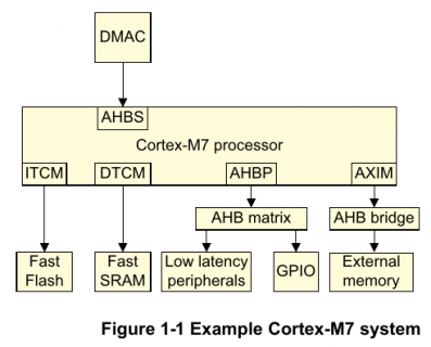
Most peripherals are connected via the AXI bus and peripheral bus bridges which run at 150 MHz, shown as "AXIM" in this diagram.

However, GPIO5-GPIO9 and FLEXIO3 are connected to the low latency bus "AHBP". It runs at the full 600 MHz.

screenshot.png
(Cortex-M7 Technical Reference Manual, DDI0489F_cortex_m7_trm.pdf, page 14)
 
It is an interesting difference in microcontroller hardware designs.

On some, the pin input (and interrupts etc.) are separate from the other peripherals on that pin, basically always enabled. This can be useful, because it lets the programmer examine the physical pin state at any time; but it also sometimes does not fit at all with the underlying hardware, for example different power and clock zones; and it can also increase total overall power consumption. Always a tradeoff..

So, on other microcontrollers, the entire GPIO facility, both input and output, is a multiplexable subcircuit, with only one of them connected to the pin at a time.

Teensy 3.5 and 3.6 are in the former category I guess, and Teensy 4.0 in the latter. It is a good idea to be aware of this facet, when picking a microcontroller.
 
Back
Top