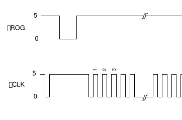
I am trying to implement the following timing diagram. The question is, is there a better (but still simple) way to do this?

So, far my idea is to setup a square wave and use a logic gate with the output from another digital pin. The code looks like this
and then to enable the clock signal, we monitor the direct clock on another pin, and when high turn on the gate,
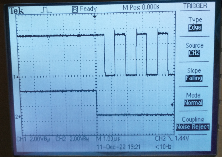
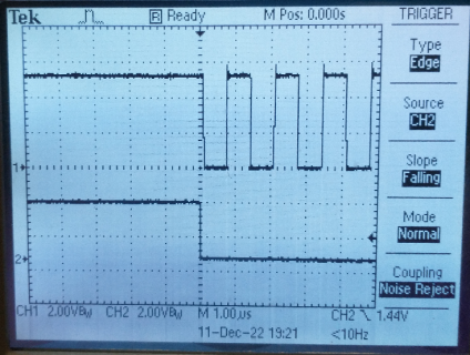
But this results in a somewhat uncontrolled interval between the gate and clock, as shown in the following two images (my old B&W tektronix).


So, is there a better more consistent way to do this?

So, far my idea is to setup a square wave and use a logic gate with the output from another digital pin. The code looks like this
Code:
analogWriteResolution(4);           // pwm range 4 bits, i.e. 2^4
analogWriteFrequency(fMPin, fM);
analogWrite(fMPin,8);              // dutycycle 50% for 2^4
and then to enable the clock signal, we monitor the direct clock on another pin, and when high turn on the gate,
Code:
while (!digitalReadFast(fMPinMonitor)){}  // Wait for high state on the clock
digitalWriteFast(CLOCKGATEPin, HIGH); // Turn the gate on
But this results in a somewhat uncontrolled interval between the gate and clock, as shown in the following two images (my old B&W tektronix).


So, is there a better more consistent way to do this?

