ILI9341 SPI and noise

barahlo

Member
Hi!
I'm working on my teensy synthesizer project and ran into a problem.
I use teensy 3.6, without an audio shield. And want the synth interface to be displayed on a ILI9341.
Every time the display updates with new text or any other graphic it produces short high pitch noise, changing SPI speed inside tft.begin() changes the pitch of that noise and at low speeds, it almost disappears but the screen updates become extremely slow, encoders and buttons unusable.
I tried hard to find anything about this issue and possible fixes but failed. Hope someone can help me with this issue

Here is a code example:

Code:
#include <Arduino.h>
#include <Audio.h>
#include <Wire.h>
#include <SD.h>
#include <SerialFlash.h>
#include <Keypad.h>

#include "SPI.h"
#include "ILI9341_t3n.h"
#include <ili9341_t3n_font_Arial.h>
#include "EncButton2.h"
#include <vector>
#include <TimerMs.h>
using namespace std;
int mydelay=500;
TimerMs tmr(mydelay, 1, 0);


AudioSynthWaveformDc     dc;            //xy=189.1428985595703,1161.2859554290771
AudioSynthWaveform       waveform; //xy=192.57142639160156,1116.0000247955322
AudioEffectEnvelope      filter_envelope;    //xy=339.14287185668945,1161.285846710205
AudioFilterStateVariable filter;        //xy=706,1130
AudioMixer4              mixer;         //xy=919,1136
AudioEffectEnvelope      envelope;    //xy=1084,1135
AudioOutputAnalogStereo  dacs1;          //xy=1349.4287490844727,1139.4285583496094
AudioConnection          patchCord1(dc, filter_envelope);
AudioConnection          patchCord2(waveform, 0, filter, 0);
AudioConnection          patchCord3(filter_envelope, 0, filter, 1);
AudioConnection          patchCord4(filter, 0, mixer, 0);
AudioConnection          patchCord5(filter, 1, mixer, 1);
AudioConnection          patchCord6(filter, 2, mixer, 2);
AudioConnection          patchCord7(mixer, envelope);
AudioConnection          patchCord8(envelope, 0, dacs1, 0);
AudioConnection          patchCord9(envelope, 0, dacs1, 1);


#define TFT_RST 8
#define TFT_DC  9   
#define TFT_CS 10
#define TFT_MOSI 11
#define TFT_MISO 12
#define TFT_SCK 14
ILI9341_t3n tft = ILI9341_t3n(TFT_CS, TFT_DC, TFT_RST, TFT_MOSI, TFT_SCK, TFT_MISO);

EncButton2<EB_ENCBTN> enc1(INPUT, 29, 30, 23);
EncButton2<EB_ENCBTN> enc(INPUT, 27, 28, 22);
EncButton2<EB_ENCBTN> enc2 (INPUT, 25, 26, 21);
EncButton2<EB_BTN> btn(INPUT, 2);           // просто кнопка

int currentWF = 0;
const byte ROWS = 6; //four rows
const byte COLS = 2; //three columns
 int activekeys=0;
int randomness=1;
char keys[ROWS][COLS] = {
  {'c','C'},
  {'e','D'},
  {'f','E'},
  {'g','F'},
  {'b','G'},
  {'B','A'}
};
byte rowPins[ROWS] = {2, 3, 4, 5, 6, 7}; //connect to the row pinouts of the kpd
byte colPins[COLS] = {0,1}; //connect to the column pinouts of the kpd

Keypad kpd = Keypad( makeKeymap(keys), rowPins, colPins, ROWS, COLS );


double freq[]={16.35, 17.32, 18.35, 19.45, 20.60, 21.83, 23.12, 24.50, 25.96, 27.50, 29.14, 30.87};
double octaves[]={1, 2, 4, 8, 16, 32, 64, 128, 256};
int octave=4;
void cfreq(char y);

void setup() {
SPI.begin();
SPI.setSCK(14);
tft.begin(20000000);
tft.setRotation(3);

tft.useFrameBuffer(true);
tft.updateChangedAreasOnly(true);
tft.setTextSize(1);
tft.fillScreen(ILI9341_BLACK);
 Serial.begin(1000000);

  AudioMemory(10);
  waveform.begin(0.2,500, currentWF);
  waveform.phase(50);
  
  mixer.gain(0, 0.5);
  mixer.gain(1, 0.0);
  mixer.gain(1, 0.0);

  dc.amplitude(1.0,500);

  filter_envelope.attack(250);
  filter_envelope.decay(200);
  filter_envelope.sustain(0.5);
  filter_envelope.release(10);
  
  filter.frequency(200);
  filter.resonance(5.0);
  filter.octaveControl(5);

  envelope.attack(250);
  envelope.decay(200);
  envelope.sustain(0.5);
  envelope.release(10);

  Serial.begin(9600);

  
}

void loop() {
  tft.drawCircle(50,40,10,ILI9341_BLUE);

tft.updateScreen();

}
 
Sorry,

I figured best to answer here versus the PM.


I don't often use the Audio board. And I am retired programmer and not an EE type. So I am not sure how much I can help you.

But here you mentioned, you are not using Audio board? So where is the noise coming from?

All I can do is throw a few darts and what I would try to see if it makes any differences.

I am assuming it is some form of RFI like feedback?

Not sure if maybe it is the wiring, or the display itself. How is it wired? i.e., your own board? breadboard? Wires...

Maybe if you showed some pictures of your setup, others may have a better idea what might be happening.

Good luck.
 
At first, i thought that it's maybe a software issue, that's why I decided to message you. Now I'm not that certain about it but maybe you or someone else can point me in a direction of the answer.
I have close to zero experience in EE and programming so this project is my way of learning it cause i find all this stuff fascinating.
Screen connected to teensy like it's described here https://www.pjrc.com/store/display_ili9341_touch.html only difference i swapped SCK pin from 13 to 14 cause led blinking was a little annoying.
I don't use Audio Adaptor Board, i use DACs (A21, A22) as output. As recommended i connected both of dacs through 10uF capacitors to 3.5 jack

Here i filmed a video with a noise:

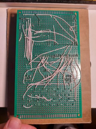
Also here is how my board looks from the other side, maybe this mess can cause noise
photo_2022-12-16_23-52-30.jpg
 
Maybe, especially since it looks like the SCK pin for SPI runs right over the top of the two DAC pins, if I am reading correctly
 
Hello, I've made a couple of Teensy based synths. One with a ST7735 and I'm currently working on one with a ILI9341. Yes, the problem is your circuit board, which will radiate and pick-up the digital noise massively. I'm using a four layer PCB (one ground plane) professionally manufactured and cannot hear the noise from the display unless I turn up the volume on the external amp to the maximum. With better separation of digital/analogue and moving toward two ground planes, I reckon I can eliminate it - I'm a hobbyist too, basically. You could try a 100ohm resistor in line with the SCK line, which might make a difference or possibly not, but you won't solve this without a well designed PCB. Have you tried listening to the digital audio output via the USB?
 
Hello, I've made a couple of Teensy based synths. One with a ST7735 and I'm currently working on one with a ILI9341. Yes, the problem is your circuit board, which will radiate and pick-up the digital noise massively. I'm using a four layer PCB (one ground plane) professionally manufactured and cannot hear the noise from the display unless I turn up the volume on the external amp to the maximum. With better separation of digital/analogue and moving toward two ground planes, I reckon I can eliminate it - I'm a hobbyist too, basically. You could try a 100ohm resistor in line with the SCK line, which might make a difference or possibly not, but you won't solve this without a well designed PCB. Have you tried listening to the digital audio output via the USB?

Yeah tried USB output just before reading your comment, sound is clear there. Probably you are right poorly designed board is a reason, which is not a surprise)
Will try to add 100ohm resistor to SCK.
Also was thinking about to try output audio through PT8211 DAC, it uses pins 9,23 and 22 maybe it will help to reduce noise cause it will be further away from SCK
 
Again, I am no EE or the like, but some of the first steps I might try
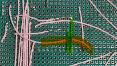
Screenshot.jpg

As the two wires I sort of highlighted in green, I believe are the DAC pins, and they also have no insolation or the like.
The one in Orange I think is the SPI clock pin, which you ran right over the top of these bare wires.
What happens if you you move the orange wire, like bend it down a ways to avoid going over those two DAC wires?

If I had some shielded coax cable/wire, I would be tempted to use it instead of the orange one and maybe connect both ends of
shield to GND... Again not sure if that would help or not. Or maybe do that for the DAC lines.

Is the Audo circuit using GND or Analog GND? Does it make a difference?
 
Again, I am no EE or the like, but some of the first steps I might try
View attachment 29977

As the two wires I sort of highlighted in green, I believe are the DAC pins, and they also have no insolation or the like.
The one in Orange I think is the SPI clock pin, which you ran right over the top of these bare wires.
What happens if you you move the orange wire, like bend it down a ways to avoid going over those two DAC wires?

If I had some shielded coax cable/wire, I would be tempted to use it instead of the orange one and maybe connect both ends of
shield to GND... Again not sure if that would help or not. Or maybe do that for the DAC lines.

Is the Audo circuit using GND or Analog GND? Does it make a difference?

You are right about the green wires, it connects dacs to a 3.5 jack, the orange one is a ground of audio input, its not active at this moment so I don't think it has any effect on a noise situation, but i will definitely move it to a different place in future.
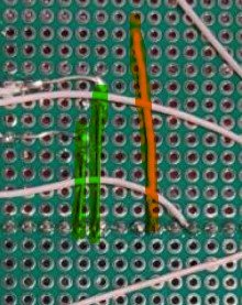
Here is a SCK wire, highlighted by orange:
dacs and SPI.jpg
Definitely will try to use shielded wire for SCK, and maybe using it for DACs is also a good idea?
I tried both GND and AGND noise present in both cases.
Thanks for a comments.
 
Back
Top