I hope posting about an older board is ok here.
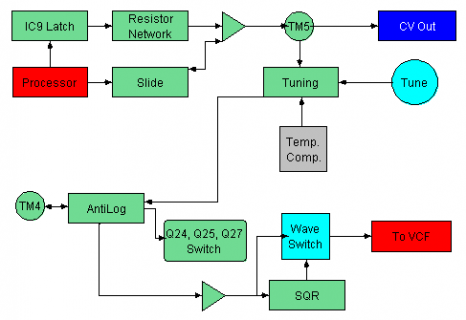
I am working on simply understanding how the RE-303 (TB303 replica) creates control voltages from the note information being output from the CPU pins to a Hex D type Flip flop.


the original CPU is a upd650 with a mask rom... anyway, I am trying to output just a middle C, 0x17 from the 6 pins of a teensy for six bits (010111).
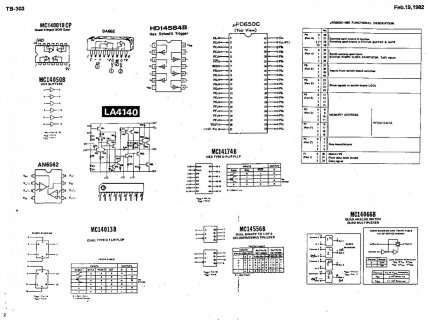
I have the code working to output 010111 from six pins on the teensy, but when I connect the output of the teensy pins to a the data input pins of the CD74AC174, I can not seem to get the latching to work from the clock.
For my simple test I connected one pin of the teensy-> PD6 to the 4174 D0 pin and the output of Q0 to an LED. I connected the reset and data in pins of the 4174 to ports that are set to the same output group as PD0, meaning , they all go high at the same time. I do see the LED blink with a delay in relation to the blinking teensy LED, my issue is however that the blinking LED I have connected to the 4174 only blinks when I touch the Reset pin or the data in pin, in a quasi random way sometimes my finger, sometimes the desk... I can't tell why the output pin is being driven high only when the data pin is temporarily connected - even if the jumper is not connected to anything. Just touching the pin activates the output then it stops after a few flashes. Should the clock be driven by an entirely separate clock output from the teensy - like a dedicated clock pin (does that exist) - should my Data in pulse be totally different in time to my reset?
PD0 ->1 ->IC9,4 ->CPU 8
PD1 ->2 ->IC9,13 ->CPU 9
PD2 ->3 ->IC9,3 ->CPU 10
PD3 ->4 ->IC9,14 ->CPU 11
PF0 ->5 ->IC9,6 ->CPU 16
PF1 ->6 ->IC9,11 ->CPU 17
PI 1 ->8 ->IC9,9 ->CPU 31 Slide
PE0 ->7 ->IC13,9 accent
PI 2 ->9 -> Gate
I am working on simply understanding how the RE-303 (TB303 replica) creates control voltages from the note information being output from the CPU pins to a Hex D type Flip flop.


the original CPU is a upd650 with a mask rom... anyway, I am trying to output just a middle C, 0x17 from the 6 pins of a teensy for six bits (010111).
I have the code working to output 010111 from six pins on the teensy, but when I connect the output of the teensy pins to a the data input pins of the CD74AC174, I can not seem to get the latching to work from the clock.
For my simple test I connected one pin of the teensy-> PD6 to the 4174 D0 pin and the output of Q0 to an LED. I connected the reset and data in pins of the 4174 to ports that are set to the same output group as PD0, meaning , they all go high at the same time. I do see the LED blink with a delay in relation to the blinking teensy LED, my issue is however that the blinking LED I have connected to the 4174 only blinks when I touch the Reset pin or the data in pin, in a quasi random way sometimes my finger, sometimes the desk... I can't tell why the output pin is being driven high only when the data pin is temporarily connected - even if the jumper is not connected to anything. Just touching the pin activates the output then it stops after a few flashes. Should the clock be driven by an entirely separate clock output from the teensy - like a dedicated clock pin (does that exist) - should my Data in pulse be totally different in time to my reset?
PD0 ->1 ->IC9,4 ->CPU 8
PD1 ->2 ->IC9,13 ->CPU 9
PD2 ->3 ->IC9,3 ->CPU 10
PD3 ->4 ->IC9,14 ->CPU 11
PF0 ->5 ->IC9,6 ->CPU 16
PF1 ->6 ->IC9,11 ->CPU 17
PI 1 ->8 ->IC9,9 ->CPU 31 Slide
PE0 ->7 ->IC13,9 accent
PI 2 ->9 -> Gate

