Teensy 4.1 Serial2 and Audio Board I2S Conflict

RubiCube

Member
Hi everyone,

I am currently working on a project where I hopefully will be able to use all 8 serial interfaces on the Teensy 4.1 to read sensor data while displaying information on a RGB Led matrix display using OctoWS2811 library.
I thought I could give it a shot to add audio as well by using the Teensy Audio Board RevD for Teensy 4.x.

I am new to the Teensy controllers but have some experience using Arduino's end ESP32's.

Currently I am only using 4 serial interfaces, Serial1-4 and only the Rx channels.
When using the Teensy Audio Board the I2S Tx/Rx will be in conflict with the Serial2 interface as I understand.
I managed to reassign Serial2 to pin 30 and 31 and Serial3 to pin 32 and 33 using setRx and setTx and it seems to work alright, at least the Rx channels. I get the sensor data that I am expecting.

The audio board works fine until the Serial interfaces are initialized and I guess the issue might be that pin 7 and 8 are not restored to be used by I2S after the reassignment.

I found a thread covering a similar issue for the Teensy 3 where Paul advised to restore the pins using PORT_PCR_MUX.

In that case this line was used:
"CORE_PIN9_CONFIG = PORT_PCR_MUX(6); // pin 9, PTC3, I2S0_TX_BCLK"

And I guess I will have to do something similar like
CORE_PIN7_CONFIG = PORT_PCR_MUX(4);
CORE_PIN8_CONFIG = PORT_PCR_MUX(6);

In this case I don't think it will help to post my code. I just want to know if the solution I have in mind should work and if so how I restore pin 7 and 8 so that they can be used by the Audio Board.
I tried adding the lines after the reassignment but it didn't work. I would be grateful for any advice.

Thanks in advance and Merry X-Max to you all!
 
Sorry I am not sure some of the above is going to work:

That is pins 7(RX) and 8(TX) are the only valid pins for Serial2 (at least for TX)
Likewise, 15(RX) and 16(TX) are the only valid pins for Serial3 (at least for TX)

That is there are no other valid pins for the TX of those two hardware Serial ports.
So setTX() of any other pin will fail to do anything.

For RX, we have a few more choices: We can use any pin that is an XBAR pin for RX.
If you are also wanting to use CTS with hardware CTS you can also use XBAR pins for that as well.
But you can only use one XBAR pin for CTS or RX on a hardware serial port.

And yes, the pins you choose for RX for those two ports are XBAR pins.
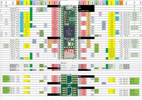
Screenshot.jpg

Note: you can use any of the XBAR pins, BUT only one of each number. That is pin 0 is XBAR17, so is pin 5,
so you can only use one of these XBAR pins for XBar...

Note: if you do the Serial2.setRX(30) call before the Serial2.begin(..) it should not muck with the default Serial pin. But the setTX will fail so you need to recover it.

If I were trying it out, I might do it something like:
Code:
	// remember the tx pin settings
	uint32_t port_config_save = *(portConfigRegister(8);
	uint32_t port_control_save = *(portControlRegister(8);
	Serial2.setRX(30); 
	Serial2.begin(xxx);
	// restore the tx pin
	*(portConfigRegister(8) = port_config_save ;
	*(portControlRegister(8) =  port_control_save ;

Warning typed on fly so probably issues.
 
Assuming you are willing to use some solder connections and delve into I2S support, IIRC, for I2S1, there are 5 data pins that can be used as inputs or outputs for I2S1. Teensy conventionally labels these as:

  • Pin 6 -- Out1D -- audio shield does not use this pin
  • Pin 7 -- Out1A -- audio shield uses this pin as the output
  • Pin 8 -- In -- audio shield uses this pin as the input
  • Pin 9 -- Out1C -- audio shield does not use this pin
  • Pin 32 -- Out1B -- audio shield does not use this pin

So clip pins 7 & 8 between the audio shield and Teensy. Then use a solder bridge to connect Teensy pin 6 to the audio shield pin 7, and Teensy pin 9 to the audio shield pin 8. You would need to figure out the I2S1 register assignments to switch the output to Out1D and the input to Out1C. Obviously you need to do some minor surgery to the audio shield board, but given the 2 pins are adjacent, it shouldn't be that hard (assuming you are doing the assembly, and not selling the Teensy and letting the user optionally plop down an audio shield on the board).

An alternative approach if you don't need the extra things that the audio shield provides (like volume control) is to use an external I2S chip, and switch to using I2S2 (pins 2-5 and pin 33). I2S2 only has 2 data pins, so you don't need to figure out how to change the defaults.

You might be able to switch to MQSR/MQSL if you just want basic sound output, but you don't use SPI for a display. Switching to S/PDIF is not an option for you since the Serial3 pins are the same as used for S/PDIF.

I haven't looked into the default pins used for the Octows2811 shield, but you may need to do some rearrangements.
 
Last edited:
Forgot to mention: Or simply don't use these two Serial objects Serial2 and Serial3.

If you really need additional Serial objects: Then maybe the FlexIO_t4 library Serial object may work sufficiently for your needs.
This one shows a TX only version, but you can also define RX only (change the two pins provided (RX, TX)

There are a few examples up under this library, like (although I removed some of the debug stuff in this listing)
Code:
// Currently setup to test Teensy Micromod, on Machine Learning connet D0 to A1
#include <FlexIO_t4.h>
#include <FlexSerial.h>

FlexSerial SerialFlex(-1, 4); // currently setup for pin 4 to test MicroMod (D0)


void setup() {
  pinMode(13, OUTPUT);
  while (!Serial && millis() < 4000);

  Serial.begin(115200);
  delay(250);
  Serial.println("Start Test Serial Flex"); Serial.flush();

  Serial3.begin(115200);  // lets start up Serial3, to see if we can receive anything from our FlexSerial
  delay(500);
  Serial.println("Before SerialFlex.begin"); Serial.flush();
  SerialFlex.begin(115200);
  Serial.println("After SerialFlex.begin"); Serial.flush();

  Serial.println("End Setup");
}

uint8_t loop_char = 'a';
void loop() {
  digitalWrite(13, !digitalRead(13));
  SerialFlex.println("abcdefghijklmnopqrstuvwxyz");
  delay(500);

}

void serialEvent3() {
  int ch;
  while ((ch = Serial3.read()) != -1) {
    Serial.write(ch);
  }
}

But should mention, that these only work on IO pins which are FlexIO pins. Which are shown in yellow in the picture in previous post:

in this like pin 2 is marked 1:4 (what this means is it is on the FlexIO1 object) and it's pin 4. As with other stuff this logical pin on that FlexIO object can only be used once if there are duplicates.
Also I don't remember if I have DMA operations on the Serial RX or not. If so only FlexIO1 and FlexIO2 have DMA support not FlexIO3. And...
 
Thanks a lot for your prompt replies and suggestions. I'll try to find some time inbetween all Christmas preparations and activities to try them out.

I just want to clarify that I wont use any Serial Tx channels so it wont matter if Tx is working or not.

The baudrate for the incoming serial data is 230400 baud on all 8 serial interfaces. Is that low enough to be suitable to be handled by any alternatives to HardwareSerial?

I have also considered using the PT8211 Audio Kit instead but I guess the same problem still remains as it also uses pin 7. I would prefer using the Audio Board as it provides Audio input as well but only output can do for now. Using an external I2S chip would of course be an alternative, as suggested.
 
Happy Holidays!

If you wish to try out FlexSerial (out of flexio_t4), there was a bug fix back in November with the RX code, which is probably not in current Released versions of Teensyduino, but should be in current beta.

Or you can pickup it up from my github project: https://github.com/kurte/flexio_t4

As I mentioned not all pins can be used for this. For example, pins 30,31 mentioned earlier are not FLXIO pins. The image I posted earlier shows which ones that are. Also the readme of the github project shows it as well.
Pins 32 and 33 are.

The baud rate should be fine. The only concern might be that, unlike hardware Serial RX which has an hardware FIFO queue, the FlexIO serial does not. So the interrupt needs to be processed per each character coming in, or some could be lost.
But as long as there is not something with higher priority taking lots of time, or something disabling interrupts for periods of time, usually is not much of a problem.
I have thought of adding in DMA support, but the issue is, for a generic case of RX, it is hard to setup the DMA, such that you both use DMA buffer and also notify the above software when more data comes in.
But may play with it at some point.
 
Unfortunately I haven't hade time to work on this until now.
I just want to ask for your advice again.

As I mentioned I need to use all 8 Serial RX channels for reading sensor data. I am also using 8 channels for controlling rgb leds with the OctoWS2811 library. However, I don't use the OctoWS2811 adaptor board. Currently I am using the UART TX pins for the leds but as I understand I am free to use almost any pin for that. It was just convenient to use the TX pins in my case. But there are many pins free that is not in use by the audio board that I can use instead.

I want to add the Audio Board to this configuration but it uses pin 7 (RX2) and pin 21 (RX5).
I can't see any other pin conflicts...

As I understand based on your suggestions I can make use of the XBAR support and use pin 30 for RX2 (Serial2.SetRX(30)). Pin 30 has XBAR number 23 which no other pin uses so it wont cause any conflicts as I understand. And I don't need to care about resetting TX pins if I don't use them I guess. Please correct me if I am wrong.

Pin 21 (RX5) doesn't support XBAR but I guess I could use the RX5 alternative pin 46 in the SDIO connector to solve the conflict with the audio board?

As the audio board uses SPI for it's SDIO I guess I will still be able to use the SD card slot on the audio board even if pin 46 is in use on the Teensy board?

I will try this out as soon as I receive the micro sdcard sniffer I have ordered. =)

Any feedback on this is appreciated

Thanks in advance
 
Back
Top