As part of my modular datalogger project, I have been developing a depth monitor for my backyard pond. The sensor just lets the pond water (more of it when the water level is higher) be part of a voltage divider, where the voltage is supplied by a Teensy.
There is a tiny bit more to this than one might think. To keep electroplating effects and biofilms from degrading the sensor, it's prudent to run the test current in one direction for the measurement, then to run it in the reverse direction for equally long, and then to stop the current until another reading is needed.
I originally connected the sensor directly to a Teensy indoors, 10 meters away. This was a bad idea, because the sensor is a high-impedance source, the cable was effectively an antenna, and the small voltage changes with changing water depth were usually lost in noise.
Now I want to put a weather-proofed Teensy out near the pond, and to let it generate a lower-impedance voltage to send to the indoor Teensy. That should be simple.
The attached .zip file includes the Teensy program and the schematic for the pondside Teensy board. The program's loop just
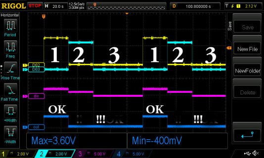
This almost works. The attached .jpg image shows two cycles of the loop. First the current flows for a reading (intervals marked 1, yellow above cyan), then it flows in reverse (intervals marked 2, cyan above yellow), then it rests (intervals marked 3, cyan and yellow both low). The voltage divider (here shown in magenta and seeing a constant "pond" resistance of 11K), seems to be doing what it should.
The DAC (here shown in blue) is not behaving as expected. Since it is set only during the 1 intervals, it should here have been constant across the screen, with a voltage similar to that produced by the divider during the 1 intervals. Instead, it drops to a low level during every 2 or 3 interval. The unrelated writes to the D02 and D03 pins seem to be resetting it.
Any suggestions will be welcome.
There is a tiny bit more to this than one might think. To keep electroplating effects and biofilms from degrading the sensor, it's prudent to run the test current in one direction for the measurement, then to run it in the reverse direction for equally long, and then to stop the current until another reading is needed.
I originally connected the sensor directly to a Teensy indoors, 10 meters away. This was a bad idea, because the sensor is a high-impedance source, the cable was effectively an antenna, and the small voltage changes with changing water depth were usually lost in noise.
Now I want to put a weather-proofed Teensy out near the pond, and to let it generate a lower-impedance voltage to send to the indoor Teensy. That should be simple.
The attached .zip file includes the Teensy program and the schematic for the pondside Teensy board. The program's loop just
- sets up a voltage across the divider
- waits for a settling time
- reads the voltage from the divider
- sets the DAC to produce that voltage
- reverses the voltage across the divider
- waits for the same settling time
- waits for a while before looping
This almost works. The attached .jpg image shows two cycles of the loop. First the current flows for a reading (intervals marked 1, yellow above cyan), then it flows in reverse (intervals marked 2, cyan above yellow), then it rests (intervals marked 3, cyan and yellow both low). The voltage divider (here shown in magenta and seeing a constant "pond" resistance of 11K), seems to be doing what it should.
The DAC (here shown in blue) is not behaving as expected. Since it is set only during the 1 intervals, it should here have been constant across the screen, with a voltage similar to that produced by the divider during the 1 intervals. Instead, it drops to a low level during every 2 or 3 interval. The unrelated writes to the D02 and D03 pins seem to be resetting it.
Any suggestions will be welcome.