T4.1 SCK on Pin 13 Fubar?

Power_Broker

Well-known member
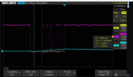
I'm trying to use a SPI display with my Teensy 4.1, but using the SCK on pin 13 is not working (see blue o-scope trace below).
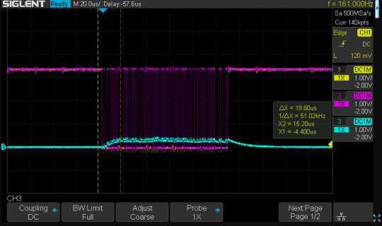
Capture.PNG

For reference I'm using the ILI9341_T4.h library (have tried others, too with no luck). Seems this is a recurring problem for Teensy 4.1s???

Is my T4.1 completely screwed? Is this a quality control issue or am I missing something?

Thanks!

**Edit, I tried this on an extra T4.1 I had lying around and got the same results :(**
 
Not shown are the code or a picture? Are any other devices connected? What does the soldering look like?

In the linked post the user confirmed soldering was clean and a simple blink failed - how about there?

No, this is not a common problem - every LED Blinks from the factory - or it doesn't leave - and should have been seen to blink on unpacking.

Beta and first release T_4.1's and some few since the (T_4.0 and T_4.1) never developed a failure on Pin13/LED ... or other pins in normal (ab)use here.
 
The code is an example of the linked library, no devices, o-scope connected directly to pin 13. Not sure why SCK isn't working for both of my T4.1. It's a really simple setup
 
I also tried with this super simple example:

Code:
#include <SPI.h>  // include the SPI library:

const int slaveSelectPin = 10;

void setup() {
  // set the slaveSelectPin as an output:
  pinMode (slaveSelectPin, OUTPUT);
  // initialize SPI:
  SPI.begin(); 
}

void loop() {
  // go through the six channels of the digital pot:
  for (int channel = 0; channel < 6; channel++) { 
    // change the resistance on this channel from min to max:
    for (int level = 0; level < 255; level++) {
      digitalPotWrite(channel, level);
      delay(10);
    }
    // wait a second at the top:
    delay(100);
    // change the resistance on this channel from max to min:
    for (int level = 0; level < 255; level++) {
      digitalPotWrite(channel, 255 - level);
      delay(10);
    }
  }
}

int digitalPotWrite(int address, int value) {
  // take the SS pin low to select the chip:
  digitalWrite(slaveSelectPin,LOW);
  //  send in the address and value via SPI:
  SPI.transfer(address);
  SPI.transfer(value);
  // take the SS pin high to de-select the chip:
  digitalWrite(slaveSelectPin,HIGH); 
}

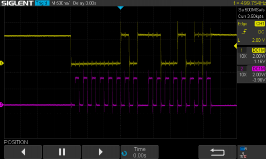
And got the following results:

Capture.PNG
 
Ran your exact code on a bare Teensy 4.1 and this is shown on the scope:

SDS00066.png

Please checkout what is externally connected to pin 13.

Paul
 
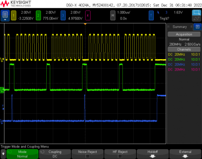
I ran the code from msg #4. These are the waveforms my scope sees on pins 10, 11, 13.

file.png

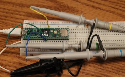
Here's a photo of the setup on my workbench, so you can see how I tested.

test.JPG

However, I did notice the code has a problem where it runs only once. Looks like the SPI library on Teensy 4 isn't happy when SPI.beginTransaction() is never called to establish the settings.

Still could not reproduce the problem where pin 13 appears to be floating.

When I run this code (which is one of the examples that comes with the SPI library) with SPI.beginTransaction, it runs much better.

Code:
#include <SPI.h>  // include the SPI library:

const int slaveSelectPin = 10;

void setup() {
  // set the slaveSelectPin as an output:
  pinMode (slaveSelectPin, OUTPUT);
  // initialize SPI:
  SPI.begin(); 
}

void loop() {
  // go through the six channels of the digital pot:
  for (int channel = 0; channel < 6; channel++) { 
    // change the resistance on this channel from min to max:
    for (int level = 0; level < 255; level++) {
      digitalPotWrite(channel, level);
      delay(10);
    }
    // wait a second at the top:
    delay(100);
    // change the resistance on this channel from max to min:
    for (int level = 0; level < 255; level++) {
      digitalPotWrite(channel, 255 - level);
      delay(10);
    }
  }
}

int digitalPotWrite(int address, int value) {
  SPI.beginTransaction(SPISettings(4000000, MSBFIRST, SPI_MODE0));
  // take the SS pin low to select the chip:
  digitalWrite(slaveSelectPin,LOW);
  //  send in the address and value via SPI:
  SPI.transfer(address);
  SPI.transfer(value);
  // take the SS pin high to de-select the chip:
  digitalWrite(slaveSelectPin,HIGH); 
  SPI.endTransaction();
}
 
As a quick sanity check, please turn on verbose output during compilation in File > Preferences. This causes Arduino IDE to print a lot of info when it compiles your program. Just before the memory usage info, are there any messages about duplicate libraries?

Normally the SPI library should always been in a sub-folder named "teesny" or "teensy4" (varies depending on Arduino 1.8.x vs 2.0.x). Just a wild guess, but maybe Arduino found some other SPI library in a folder like Documents/Arduino/libraries and used it rather than the SPI library meant for Teensy? (and by some hard-to-imagine circumstance code not meant for Teensy somehow compiled without any errors and was able to run, but of course didn't do anything on pin 13). Ok, that seems pretty unlikely... but just a blind guess at how this could have happened, other than the obvious answer that maybe pin 13 simply isn't soldered or otherwise isn't actually connected.
 
Also a further test, since pin 13 has the orange LED connected, try running File > Examples > 01.Basics > Blink.

If the orange LED blinks, that can at least confirm whether pin 13 on your board is still connected (to the LED) and working.

Edit: when (if) you see the orange LED blinking... then look to see whether your oscilloscope can observe the voltage changing.
 
Last edited:
Back
Top