Custom T4.1 with Audio board (no sound)

yeahtuna

Well-known member
I've built a custom T4.1 with an integrated STGL5000. I had to use the 20 pin version and the 32 pin one is (at least was) out of stock. It seems to work fine (no initialization errors), but I'm getting no audio using the ToneSweep example. I've including my schematic of the audio portion. Can anyone spot an issue or suggest how I might go about testing my circuit?
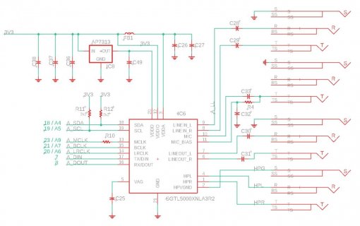
audioBoard.jpg
 
Last edited:
I've checked all the clock lines with a scope and they seem to be getting signals. VDDD is 1.57V, VDDIO and VDDA are both 3.3V. According to the the SGTL5000 datasheet, VAG should be showing VDDA/2 (1.65V), but my multimeter is showing 0V, so it looks like the SGTL5000 is not powering up properly.
 
Last edited:
Really looks like it should work.

I can confirm the 20 pin chip does work. We'll have it on the next batch of audio shields, because same situation, 32 pin version is currently unavailable.

Are you sure your chip has the bottom pad properly soldered? On the 20 pin part it is the only GND connection. The chip won't work if that pad isn't soldered to GND.
 
Resoldered and still no go. Something that's off is the VDDD (1.57V). I'm using AP7313-12SA, so it should be 1.2V. I pulled the SGTL5000 off the board again, and the AP7313 is measuring 1.2V as it should, so something is definitely not right.
 
Last edited:
I removed the AP7313-12, and the VDDD pin of the SGTL5000 is still being driven to 1.57V.

I've seen in some other posts that say VDDD needs to be 1.8V. Do I need to use AP7313-18SA instead? The SGTL5000 datasheet seems to indicate that anything from 1.1V to 2V should work.
 
Last edited:
I got the 1.8V AP7313 and still no joy. Upon further inspection, my A5 (19) pin is connected to pin L5 or the MIMXRT1062D when it should be connected to J11. I guess I'll need to do another run of the PCB.
 
Back
Top