Hi,
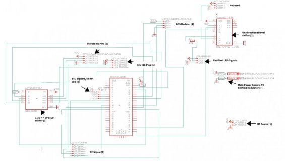
I designed a very basic PCB to mount the Teensy 4.1 with a variety of sensors. With a first test run, with only some components in place, everything worked fine. Then, adding different components before trying again resulted in the Teensy being fried. First, here is a list of things that are in use, referenced in the schematic. Note that some components were not in use at this point, but I included them to avoid further fries. Components in place in the first run are marked by ++ and components in place in the second run, which fried the board are marked by --. The numbers corresponding to the labels on the schematic.
[1] NRF24L01+ RF Module with 5V breakout board. The breakout board allows to supply 5V to the RF Module but leaves the signal lines unchanged at 3.3V (measured it to make sure) as seen here AdapterBoard --
[2] Adafruit 74hc595 uni-directional level shifter ++ --
[3] Sparkfun Bi-Directional Logic Level-Shifter 3.3V <-> 5V ++ --
[4] GY neo6mv2 GPS Module (not used so far)
[5] BMX160 IMU (not used so far)
[6] HC SR 04 Ultrasonic sensor (not used so far)
[7] External Shifting Power Regulator LM2596s. Connected to a 3S LiPo and set to 4.992V --
[8] HAKRC 4 in 1 20A BLHeLi_S ESC. This ESC is supplied externally by the same battery as [7] though the teensy and the ESC only share GND and Signals ++
In short, in the first test run, Teensy got power by USB, ESC was supplied by battery and ESC signals connected to the Teensy. In the second run, the Teensy was supplied by the Shifting Regulator and connected to the RF Module. After the second run, the teensy 3.3V reads 0.02V, the resistance between GND and 3.3V is very low and the Teensy isn't responsive so I assume it is fried. There is no obvious short due to metal on the board.
Here is the schematic:

I have 3 questions:
1. What could have caused my Teensy to die? Any obvious mistakes in the setup?
2. How to avoid 1
3. Concerning the components that were not in use so far: is there anything that risks frying my Teensy again?
Best regards
I designed a very basic PCB to mount the Teensy 4.1 with a variety of sensors. With a first test run, with only some components in place, everything worked fine. Then, adding different components before trying again resulted in the Teensy being fried. First, here is a list of things that are in use, referenced in the schematic. Note that some components were not in use at this point, but I included them to avoid further fries. Components in place in the first run are marked by ++ and components in place in the second run, which fried the board are marked by --. The numbers corresponding to the labels on the schematic.
[1] NRF24L01+ RF Module with 5V breakout board. The breakout board allows to supply 5V to the RF Module but leaves the signal lines unchanged at 3.3V (measured it to make sure) as seen here AdapterBoard --
[2] Adafruit 74hc595 uni-directional level shifter ++ --
[3] Sparkfun Bi-Directional Logic Level-Shifter 3.3V <-> 5V ++ --
[4] GY neo6mv2 GPS Module (not used so far)
[5] BMX160 IMU (not used so far)
[6] HC SR 04 Ultrasonic sensor (not used so far)
[7] External Shifting Power Regulator LM2596s. Connected to a 3S LiPo and set to 4.992V --
[8] HAKRC 4 in 1 20A BLHeLi_S ESC. This ESC is supplied externally by the same battery as [7] though the teensy and the ESC only share GND and Signals ++
In short, in the first test run, Teensy got power by USB, ESC was supplied by battery and ESC signals connected to the Teensy. In the second run, the Teensy was supplied by the Shifting Regulator and connected to the RF Module. After the second run, the teensy 3.3V reads 0.02V, the resistance between GND and 3.3V is very low and the Teensy isn't responsive so I assume it is fried. There is no obvious short due to metal on the board.
Here is the schematic:

I have 3 questions:
1. What could have caused my Teensy to die? Any obvious mistakes in the setup?
2. How to avoid 1
3. Concerning the components that were not in use so far: is there anything that risks frying my Teensy again?
Best regards
Last edited:

