Two Teensy 4.1 cannot communicate via NRF2401

Hat786

Member
Hello, I cannot get my NRF24Liter01/PA/LNA to communicate with each other, I am using two teensy 4.1. I am using a 100uf capacitor, but I'm unable to use a dedicated source until I get a 3.3v regulator.
The code I'm using is from a youtube video. I have also used the NRF24 library with no luck (the radio is not responding). I removed the if radio available statement and just got a bunch of random symbols (the serial monitor rate is correctly set)
Am I doing something wrong, or is the transceiver module not working? Any help is appreciated, been trying to figure this out for a few days.


Here is the connection from the NRF24L01 to the Teensy 4.1


NRF24L01 -> Teensy 4.1
V+ -> 3.3V
GND -> GND
CSN -> 38
CS -> 37
MOSI -> 11
SCK -> 27
MISO - 12

Edit: I changed the code to have RF24 radio(37, 38) for both transmitter and receiver.
 

Attachments

  • Screenshot 2023-01-05 141804.jpg
    Screenshot 2023-01-05 141804.jpg
    95.5 KB · Views: 55
Last edited:
You state "CSN -> 38, CS -> 37" but your code states "RF24 radio(36, 37);".
Could that be the problem? It should be RF24 radio(CE, CSN).

Paul
 
You state "CSN -> 38, CS -> 37" but your code states "RF24 radio(36, 37);".
Could that be the problem? It should be RF24 radio(CE, CSN).

Paul

Hi Paul, sorry for the Inaccurate information I provided, I was playing around with it and forgot to change the code back. I tried with RF24 radio(37, 38), but it just gave me a different symbol text.

Screenshot 2023-01-05 153421.jpg
 
Last edited:
Couple of comments:
1. You may want to add radio.setChannel(100); to both the RX and TX sketch to make sure the modules are using the same RF channel.
2. Is there a specific reason for using pin 27 as SCK and not pin 13 since pin 27 is the SCK for the second SPI interface while you use MOSI and MISO of the primary SPI interface. I doubt whether this will work.
3. You did not add radio.begin(); to the TX sketch.

Hope this helps,
Paul
 
Hi, Paul I seriously appreciate the help, I did those changes with sadly no luck. I have some good news though, I followed along with a tutorial and made some progress. Don't worry if you don't have any ideas/fixes, you have helped me out a lot, so thankyou.


New Pin Layout (I switched to pin 13 since there was no reason to use pin 27)
CE - 0
CSN - 1
SCK - 13
MOSI - 11
MISO - 12
VCC - 3.3V (250 mA max)
GND - GND

I also tried CE as 37 and CSN as 36, but I got the same result.

Tutorial Link: https://forum.arduino.cc/t/simple-nrf24l01-2-4ghz-transceiver-demo/405123
Tutorial Type: "Simple one way transmission"

Results:

The transmitter tells me "Data Sent Message 0-9 Acknowledge received". This means the transmitter knows the message was received and is counting up from 0 to 9, then going back to 0. It works 100% of the time unless I make interference.
The receiver tells me "Data Received", but beside it, it's blank. Unless I make interference, then it's a bunch of random symbols like the above screenshot from my last message.

I'm convinced my pins are wrong. I tried switching nrf24 modules to one with no antenna, but that had no impact. I also used a different code where I would send a struct data, I sent a byte over with the number 7, but it only returned 0 for interference or 255 when there is no interference.
 
Well, I tried to make a working setup using the code from the tutorial you linked to but could not get it to work...

So I changed to another sketch that I know I had working before: File > Examples > RF24 > GettingStarted.ino.
Changed one line of code to RF24 radio(0, 1);.
And that worked fine!

Here is the output using TyCommander to show both serial ports:

RF24test.jpg

Transmitting by the T3.2 and receiving by the T4.1 also worked fine.

You can download TyCommander from GitHub. Extract the ZIP file and run TyCommander.exe.

For reference, here is the exact code I uploaded to both the Teensy 4.1 and the Teensy 3.2:
Code:
/*
 * See documentation at https://nRF24.github.io/RF24
 * See License information at root directory of this library
 * Author: Brendan Doherty (2bndy5)
 */

/**
 * A simple example of sending data from 1 nRF24L01 transceiver to another.
 *
 * This example was written to be used on 2 devices acting as "nodes".
 * Use the Serial Monitor to change each node's behavior.
 */
#include <SPI.h>
#include "printf.h"
#include "RF24.h"

// instantiate an object for the nRF24L01 transceiver
RF24 radio(0, 1);  // using pin 7 for the CE pin, and pin 8 for the CSN pin

// Let these addresses be used for the pair
uint8_t address[][6] = { "1Node", "2Node" };
// It is very helpful to think of an address as a path instead of as
// an identifying device destination

// to use different addresses on a pair of radios, we need a variable to
// uniquely identify which address this radio will use to transmit
bool radioNumber = 1;  // 0 uses address[0] to transmit, 1 uses address[1] to transmit

// Used to control whether this node is sending or receiving
bool role = false;  // true = TX role, false = RX role

// For this example, we'll be using a payload containing
// a single float number that will be incremented
// on every successful transmission
float payload = 0.0;

void setup() {

  Serial.begin(115200);
  while (!Serial) {
    // some boards need to wait to ensure access to serial over USB
  }

  // initialize the transceiver on the SPI bus
  if (!radio.begin()) {
    Serial.println(F("radio hardware is not responding!!"));
    while (1) {}  // hold in infinite loop
  }

  // print example's introductory prompt
  Serial.println(F("RF24/examples/GettingStarted"));

  // To set the radioNumber via the Serial monitor on startup
  Serial.println(F("Which radio is this? Enter '0' or '1'. Defaults to '0'"));
  while (!Serial.available()) {
    // wait for user input
  }
  char input = Serial.parseInt();
  radioNumber = input == 1;
  Serial.print(F("radioNumber = "));
  Serial.println((int)radioNumber);

  // role variable is hardcoded to RX behavior, inform the user of this
  Serial.println(F("*** PRESS 'T' to begin transmitting to the other node"));

  // Set the PA Level low to try preventing power supply related problems
  // because these examples are likely run with nodes in close proximity to
  // each other.
  radio.setPALevel(RF24_PA_LOW);  // RF24_PA_MAX is default.

  // save on transmission time by setting the radio to only transmit the
  // number of bytes we need to transmit a float
  radio.setPayloadSize(sizeof(payload));  // float datatype occupies 4 bytes

  // set the TX address of the RX node into the TX pipe
  radio.openWritingPipe(address[radioNumber]);  // always uses pipe 0

  // set the RX address of the TX node into a RX pipe
  radio.openReadingPipe(1, address[!radioNumber]);  // using pipe 1

  // additional setup specific to the node's role
  if (role) {
    radio.stopListening();  // put radio in TX mode
  } else {
    radio.startListening();  // put radio in RX mode
  }

  // For debugging info
  // printf_begin();             // needed only once for printing details
  // radio.printDetails();       // (smaller) function that prints raw register values
  // radio.printPrettyDetails(); // (larger) function that prints human readable data

}  // setup

void loop() {

  if (role) {
    // This device is a TX node

    unsigned long start_timer = micros();                // start the timer
    bool report = radio.write(&payload, sizeof(float));  // transmit & save the report
    unsigned long end_timer = micros();                  // end the timer

    if (report) {
      Serial.print(F("Transmission successful! "));  // payload was delivered
      Serial.print(F("Time to transmit = "));
      Serial.print(end_timer - start_timer);  // print the timer result
      Serial.print(F(" us. Sent: "));
      Serial.println(payload);  // print payload sent
      payload += 0.01;          // increment float payload
    } else {
      Serial.println(F("Transmission failed or timed out"));  // payload was not delivered
    }

    // to make this example readable in the serial monitor
    delay(1000);  // slow transmissions down by 1 second

  } else {
    // This device is a RX node

    uint8_t pipe;
    if (radio.available(&pipe)) {              // is there a payload? get the pipe number that recieved it
      uint8_t bytes = radio.getPayloadSize();  // get the size of the payload
      radio.read(&payload, bytes);             // fetch payload from FIFO
      Serial.print(F("Received "));
      Serial.print(bytes);  // print the size of the payload
      Serial.print(F(" bytes on pipe "));
      Serial.print(pipe);  // print the pipe number
      Serial.print(F(": "));
      Serial.println(payload);  // print the payload's value
    }
  }  // role

  if (Serial.available()) {
    // change the role via the serial monitor

    char c = toupper(Serial.read());
    if (c == 'T' && !role) {
      // Become the TX node

      role = true;
      Serial.println(F("*** CHANGING TO TRANSMIT ROLE -- PRESS 'R' TO SWITCH BACK"));
      radio.stopListening();

    } else if (c == 'R' && role) {
      // Become the RX node

      role = false;
      Serial.println(F("*** CHANGING TO RECEIVE ROLE -- PRESS 'T' TO SWITCH BACK"));
      radio.startListening();
    }
  }

}  // loop

Here the photo's of my setup:

IMG_20230107_093912.jpg

IMG_20230107_094109.jpg

IMG_20230107_094011.jpg

IMG_20230107_093947.jpg

Paul
 
Including code as pictures rather than in [ code ]...[ /code ] blocks makes it harder for others to help you.

From this code fragment:

Code:
   char text[] = "";
   radio.read(&text, sizeof(text));

ask yourself 2 questions:

1. How many bytes are you asking the radio to read?
2. Assuming the radio actually returned anything, where would it store it?

And from this code fragment:

Code:
void loop() {
  const char text[32] = "Hello World";
  radio.write(&text, sizeof(text));
}

ask yourself how often you are asking the radio to transmit.

The following slightly modified sketches work.

Transmitter
Code:
#include "nRF24L01.h"
#include "RF24.h"
#include "SPI.h"

// Transmitter

RF24 radio(37, 38);
const byte address[6] = "00001";

void setup() {
   Serial.begin(9600);

   if( !radio.begin() ) {
      Serial.println("Radio not responding");
      while(true);
   }
   radio.openWritingPipe(address);
   radio.setDataRate(RF24_250KBPS);
   radio.setPALevel(RF24_PA_MIN);
   radio.stopListening();
}

void loop() {
  const char text[] = "Hello World";
  radio.write(text, sizeof(text));
  delay(1000);
}

Receiver
Code:
#include "nRF24L01.h"
#include "RF24.h"
#include "SPI.h"

// Receiver

RF24 radio(37, 38);
const byte address[6] = "00001";

void setup() {
   Serial.begin(9600);
   if( !radio.begin() ) {
      Serial.println("Radio not responding");
      while(true);
   }
   radio.openReadingPipe(0, address);
   radio.setDataRate(RF24_250KBPS);
   radio.setPALevel(RF24_PA_MIN);
   radio.startListening();
}

void loop() {
   char text[80];
   if( radio.available() ) {
      radio.read(text, sizeof(text));
      Serial.println(text);
   }
}
 
Well, I tried to make a working setup using the code from the tutorial you linked to but could not get it to work...

So I changed to another sketch that I know I had working before: File > Examples > RF24 > GettingStarted.ino.
Changed one line of code to RF24 radio(0, 1);.
And that worked fine!

Here is the output using TyCommander to show both serial ports:

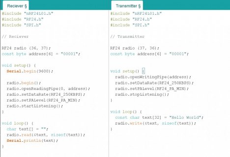
View attachment 30097

Transmitting by the T3.2 and receiving by the T4.1 also worked fine.

You can download TyCommander from GitHub. Extract the ZIP file and run TyCommander.exe.

For reference, here is the exact code I uploaded to both the Teensy 4.1 and the Teensy 3.2:
Code:
/*
 * See documentation at https://nRF24.github.io/RF24
 * See License information at root directory of this library
 * Author: Brendan Doherty (2bndy5)
 */

/**
 * A simple example of sending data from 1 nRF24L01 transceiver to another.
 *
 * This example was written to be used on 2 devices acting as "nodes".
 * Use the Serial Monitor to change each node's behavior.
 */
#include <SPI.h>
#include "printf.h"
#include "RF24.h"

// instantiate an object for the nRF24L01 transceiver
RF24 radio(0, 1);  // using pin 7 for the CE pin, and pin 8 for the CSN pin

// Let these addresses be used for the pair
uint8_t address[][6] = { "1Node", "2Node" };
// It is very helpful to think of an address as a path instead of as
// an identifying device destination

// to use different addresses on a pair of radios, we need a variable to
// uniquely identify which address this radio will use to transmit
bool radioNumber = 1;  // 0 uses address[0] to transmit, 1 uses address[1] to transmit

// Used to control whether this node is sending or receiving
bool role = false;  // true = TX role, false = RX role

// For this example, we'll be using a payload containing
// a single float number that will be incremented
// on every successful transmission
float payload = 0.0;

void setup() {

  Serial.begin(115200);
  while (!Serial) {
    // some boards need to wait to ensure access to serial over USB
  }

  // initialize the transceiver on the SPI bus
  if (!radio.begin()) {
    Serial.println(F("radio hardware is not responding!!"));
    while (1) {}  // hold in infinite loop
  }

  // print example's introductory prompt
  Serial.println(F("RF24/examples/GettingStarted"));

  // To set the radioNumber via the Serial monitor on startup
  Serial.println(F("Which radio is this? Enter '0' or '1'. Defaults to '0'"));
  while (!Serial.available()) {
    // wait for user input
  }
  char input = Serial.parseInt();
  radioNumber = input == 1;
  Serial.print(F("radioNumber = "));
  Serial.println((int)radioNumber);

  // role variable is hardcoded to RX behavior, inform the user of this
  Serial.println(F("*** PRESS 'T' to begin transmitting to the other node"));

  // Set the PA Level low to try preventing power supply related problems
  // because these examples are likely run with nodes in close proximity to
  // each other.
  radio.setPALevel(RF24_PA_LOW);  // RF24_PA_MAX is default.

  // save on transmission time by setting the radio to only transmit the
  // number of bytes we need to transmit a float
  radio.setPayloadSize(sizeof(payload));  // float datatype occupies 4 bytes

  // set the TX address of the RX node into the TX pipe
  radio.openWritingPipe(address[radioNumber]);  // always uses pipe 0

  // set the RX address of the TX node into a RX pipe
  radio.openReadingPipe(1, address[!radioNumber]);  // using pipe 1

  // additional setup specific to the node's role
  if (role) {
    radio.stopListening();  // put radio in TX mode
  } else {
    radio.startListening();  // put radio in RX mode
  }

  // For debugging info
  // printf_begin();             // needed only once for printing details
  // radio.printDetails();       // (smaller) function that prints raw register values
  // radio.printPrettyDetails(); // (larger) function that prints human readable data

}  // setup

void loop() {

  if (role) {
    // This device is a TX node

    unsigned long start_timer = micros();                // start the timer
    bool report = radio.write(&payload, sizeof(float));  // transmit & save the report
    unsigned long end_timer = micros();                  // end the timer

    if (report) {
      Serial.print(F("Transmission successful! "));  // payload was delivered
      Serial.print(F("Time to transmit = "));
      Serial.print(end_timer - start_timer);  // print the timer result
      Serial.print(F(" us. Sent: "));
      Serial.println(payload);  // print payload sent
      payload += 0.01;          // increment float payload
    } else {
      Serial.println(F("Transmission failed or timed out"));  // payload was not delivered
    }

    // to make this example readable in the serial monitor
    delay(1000);  // slow transmissions down by 1 second

  } else {
    // This device is a RX node

    uint8_t pipe;
    if (radio.available(&pipe)) {              // is there a payload? get the pipe number that recieved it
      uint8_t bytes = radio.getPayloadSize();  // get the size of the payload
      radio.read(&payload, bytes);             // fetch payload from FIFO
      Serial.print(F("Received "));
      Serial.print(bytes);  // print the size of the payload
      Serial.print(F(" bytes on pipe "));
      Serial.print(pipe);  // print the pipe number
      Serial.print(F(": "));
      Serial.println(payload);  // print the payload's value
    }
  }  // role

  if (Serial.available()) {
    // change the role via the serial monitor

    char c = toupper(Serial.read());
    if (c == 'T' && !role) {
      // Become the TX node

      role = true;
      Serial.println(F("*** CHANGING TO TRANSMIT ROLE -- PRESS 'R' TO SWITCH BACK"));
      radio.stopListening();

    } else if (c == 'R' && role) {
      // Become the RX node

      role = false;
      Serial.println(F("*** CHANGING TO RECEIVE ROLE -- PRESS 'T' TO SWITCH BACK"));
      radio.startListening();
    }
  }

}  // loop

Here the photo's of my setup:

View attachment 30098

View attachment 30099

View attachment 30100

View attachment 30101

Paul

Thank you so much for going out of your way to give me the code and replicate my issue, it really means a lot. Also, the software you recommended is awesome.

I replicated the code and the pins but sadly it told me the radio isn't responding. But since I know it works for you, it's got to be something on my end, and the only thing I can think of is the solder for the pins (I did it myself with not too much experience). I'm going to re-solder 1 Teensy and the other I try to solder it better. Sorry, that I wasn't able to get it working, but without your help, I believe I still wouldn't have been able to narrow it down to the soldering.

Thanks again Paul for the help you have provided.
 
Including code as pictures rather than in [ code ]...[ /code ] blocks makes it harder for others to help you.

From this code fragment:

Code:
   char text[] = "";
   radio.read(&text, sizeof(text));

ask yourself 2 questions:

1. How many bytes are you asking the radio to read?
2. Assuming the radio actually returned anything, where would it store it?

And from this code fragment:

Code:
void loop() {
  const char text[32] = "Hello World";
  radio.write(&text, sizeof(text));
}

ask yourself how often you are asking the radio to transmit.

The following slightly modified sketches work.

Transmitter
Code:
#include "nRF24L01.h"
#include "RF24.h"
#include "SPI.h"

// Transmitter

RF24 radio(37, 38);
const byte address[6] = "00001";

void setup() {
   Serial.begin(9600);

   if( !radio.begin() ) {
      Serial.println("Radio not responding");
      while(true);
   }
   radio.openWritingPipe(address);
   radio.setDataRate(RF24_250KBPS);
   radio.setPALevel(RF24_PA_MIN);
   radio.stopListening();
}

void loop() {
  const char text[] = "Hello World";
  radio.write(text, sizeof(text));
  delay(1000);
}

Receiver
Code:
#include "nRF24L01.h"
#include "RF24.h"
#include "SPI.h"

// Receiver

RF24 radio(37, 38);
const byte address[6] = "00001";

void setup() {
   Serial.begin(9600);
   if( !radio.begin() ) {
      Serial.println("Radio not responding");
      while(true);
   }
   radio.openReadingPipe(0, address);
   radio.setDataRate(RF24_250KBPS);
   radio.setPALevel(RF24_PA_MIN);
   radio.startListening();
}

void loop() {
   char text[80];
   if( radio.available() ) {
      radio.read(text, sizeof(text));
      Serial.println(text);
   }
}

Thank you for letting me know about the code, I'll remember to do that next time. I did try using the modified code, but it gave me random symbols, so I'll try re-soldering my pins since I know everything else is correct.
 
Update...

After modifying the code a bit to wait until the radio is on before doing anything, it is only transmitting data, never receiving.
 
Last edited:
Back
Top