No UART RX, not even when loopback from TX. Teensy 3.2

Hi all!

I have a Teensy 3.2 which I try to use to communicate with my Icom radio over Ci-V at 19200 Baud.
I can transmit and change settings on the radio but even if I loop the TX directly to the RX or to another serial RX I cannot read any serial data.

Do I have to do anything else than just Serial1.begin(19200, SERIAL_8N0); to set up the RX pin as input for data?
I primarily use Serial1 as HW serial port, i.e. connect TX to pin 1 and RX to pin 0. I have also tried a patch between pin 0 and pin 7 and try to read using Serial3 but that don't work either.
I can see with the oscilloscope I have the same waveform at my RX-pin as I have at my TX-pin when sending data over TX manually via the USB interface.

Any suggestion what to try next?

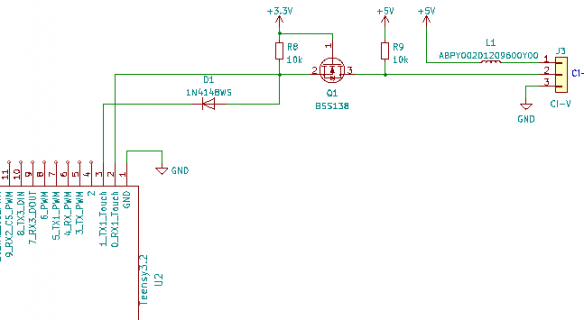
My wireing is as follows. The Icom Ci-V bus is a single wire pulled up open collector bus.
The FET is a level translator of normal kind good for much more than 19200 baud:
Capture.PNG
The dotted line is my patch for trying to read using Serial3.

My code for initalizing and read/write is as follows:


Code:
void initCAT(){
  #ifdef CAT_REPEATER
    Serial.begin(CAT_BAUD, SERIAL_8N1);
    Serial1.begin(CAT_BAUD, SERIAL_8N1);
    //Serial3.begin(CAT_BAUD, SERIAL_8N1);
  #endif  
}


void serviceCAT() {
    // USB->CAT
    int c = Serial.read();                  // read from USB
    if (c != -1) {                          // got anything?
        Serial1.write(c);                   // Yes write char to UART (CAT)
        //Serial3.write(c);                   // Yes write char to UART (CAT)
    }

    // CAT -> USB
    c = Serial1.read();                       // read from UART
    //c = Serial3.read();                       // read from UART
    if (c != -1) {                            // got anything?
      Serial.write(c);                        // Yes write ro USB
    }
}
 

Attachments

  • Capture.PNG
    Capture.PNG
    7.8 KB · Views: 32
Last edited by a moderator:
Perhaps it's better to read serial data like this:
Code:
// CAT -> USB
if (Serial1.available() > 0) {  // got anything?
  int c = Serial1.read();  // read from UART
  Serial.write(c);         // Yes write to USB
}

See also this page.

Paul
 
Edited p#1 to use CODE # marking to preserve code indenting.

Looking at the schematic it shows a 'DOT' connection on the Tx and Rx lines going to a single pin on the ICOM end?

The Rx and Tx lines shouldn't be tied together as full duplex on the Teensy side?

Assuming the GND is common to both devices.
 
Thank you Paul
I have tried that way as well but no luck with that either.
I'd also want to add that it is supposed to be 8bit, one startbit, one stopbit and no parity according to Icom and this works to control the radio but still no data even throught the loopback.

I have also found the page you refer to.
It is as if the RX is not detecting the data even though I see it is there.

I forgot to say I use the Teensyduino IDE to program but that is probably obvious as I use the functions there to set things up.
 
The Rx and Tx lines shouldn't be tied together as full duplex on the Teensy side?
I guess it's possible to operate in half duplex mode. But you will see all data transmitted also on the receiving pin [kind of local echo].

Paul
 
I'm aware of the fact that my code, if working, would make a great infinite echo loop.
The Icom bus is an open collector bus where collisions will occur.
I need to take care of that in the code but first I must get the RX to work at all.

Thanks for fixing my indentation :)
I'm not used to the forum syntax yet.
 
Last edited:
Apparently it's not just that simple to realize half duplux, see this thread.
More threads to be found when you Google for "teensy serial half duplex".

Paul
 
Note: the current versions of Teensyduino have a halffduplex mode built in. Which you only connect up to the TX pin, and it turns that pin into Bidirectional. When you do SerialX.write()... it sets the pin for output, when the output queue is empty and the last bits are sent out, it sets the pin into receive mode.

Somre reason, my gut does not like your schematic. Looks like when you output something out the TX pin it is trying to go through the diode ... Could be right but feels wrong.
 
Thank you all for trying to help me.
I really appreciate your effort to help but my question is not how to take care of the half duplex problem in software but why my receive is not working at all. I could just ignore the sending part and just listen as my main goal is to detect when the radio changes mode. I understand my problem might lay in the implementation of the hardware but the loopback should at least work to see everything I write as I know it is going out as my radio respond to it.
My problem might be due to the hardware implementation, hence my schematic.

Kurt: The diode to the TX line is to emulate an open collector, i.e. When TX is generating 3.3V nothing goes out of through the diode. The line is however high due to the pull-up resistor. When the TX is low, close to ground, the 3.3V through the pull-up is grounded through the diode and hence the signal is low. It is a kind of wired OR. Open collector is a bus where multiple drivers may pull the line low but only the pull-up can drive the line high.
The only drawbacks are that the low-level on the bus will be whatever the diode has as forward voltage and the rise time is dependant of the pull-up resistor value in combination with the total capacitance of the bus. I'm using an 1N4148 diode to the TX and my problem is not with the TX but the RX.
The FET construction is a well known level converter design. Google "level converter FET" and you will find loads of information.

I do see the serial data going out at both RX and TX pins and the data coming in on the RX pin but nothing is detected as data. Not even when I route the RX to Serial3 RX where the TX is unconnected, i.e. it is a read-only port. I'm using Hercules monitor from www.hw-group.com which is set to translates non-writable characters to hexadecimal codes so it is not the terminal just not able to write what is relayed.

I have read in the documentation the serial ports are TTL-level but I don't fully believe that it is true as the device is a 3.3V device with 5V tolerant IO and TTL is 5V level signalling in both directions. I have therefor implemented a level switch between 3.3V and 5V to be gentle to the processor. The Ci-V bus is not said to be TTL so this implementation also protects the IO from over voltages on the bus.

So, back to the original question; Do I normally have to do something other then Serial1.begin (or whatever port I use) to initiate the RX-pin fully?
Maybe there is somehing else that can make life harder for the Serial ports receive function? Such as interrupts and the like?

The software is an audio filter I got originally from github that I'm trying to adapt to my Icom rig. It is originally written for a Yaesu radio which is full duplex so there should not be any shady coding for the serial ports.
This is the original code:
https://github.com/gi1mic/19Dollar-DSP-Filter


Apparently it's not just that simple to realize half duplux, see this thread.
More threads to be found when you Google for "teensy serial half duplex".

Paul
 
the current versions of Teensyduino have a halffduplex mode built in
Interesting, didn't know that.
But how would I code for that? Is it as simple as this?
Code:
void setup() {
  Serial1.begin(19200, SERIAL_8N1_HALF_DUPLEX);
}

void loop() {
  Serial1.write(0xAA);               // write something
  delay(10);                         // turnaround time? 
  if (Serial1.available() > 0) {     // listen
    int c = Serial1.read();
    Serial.write(c);                 // send over USB to serial monitor
  }
}

What is the minimum turnaround time? Output queue empty [depends on baudrate I guess] + pin into receive mode = ?

Thanks,
Paul
 
when you do Serial1.begin() it will enable the RX of the UART. The TX is only enabled when there is stuff to output or has been output.

As mentioned in the other thread, I have done half duplex several different ways. Mainly to talk to Dynamixel servos.
Sorry, I should have noticed that the BSS138 part is simply the TTL level shifter setup (like in the Adafruit or Sparkfun bidirectional level shifter), then the diode for the open drain.

Side note: The Teensy hardware does allow you to setup the TX pin in open drain mode, by using the setTX method:
Code:
	void setTX(uint8_t pin, bool opendrain=false);

I tried something similar a couple of years ago and did not like it as well as some other approaches, so went back to those.
With the TX pin connected to the RX pin, It would echo everything that the TX pin sent back to the RX pin. So my could would be forced to know when the TX completed, and then
would need to do stuff like: Serial1.clear(); Or loop doing: while (Serial1.read() != -1) ;
Before I could then wait for response back from Servos.

Sort of like:
Code:
Serial1.write(packet, sizeof(packet));
Serial1.flush(); // make sure it all goes out
while (Serial1.read() != -1) ;

That is I would block until everything was fully output...

So I mostly went back to using 3 pins (TX, RX, write_enable). And then register the write_enable pin with the Serial port.
Code:
Serial1.transmitterEnable(the_write_enable_pin);
That way the code leaves the setup ready to receive data, only when you do serial outputs, does it set it into write mode. When the queue is empty and we receive the interrupt that the transmit has completed, will we then
atomically switch back to rx mode.

If I were trying your setup, would probably setup a logic analyzer on the TX, RX and other side pins and see what the signals look like.
 
Trying to answer your original question without all this extra stuff about half duplex and external circuitry...

So, back to the original question; Do I normally have to do something other then Serial1.begin (or whatever port I use) to initiate the RX-pin fully?

All you need for the RX1 pin to work correctly is Serial1.begin() and Serial1.read(). Use of Serial1.available() is optional. Using only Serial1.read() and checking for -1 is perfectly fine.

So the answer is no, you don't need something other than that.

From the tone of your question, I'm getting the impression you might believe Teensy's Serial1 receive code is buggy or otherwise doesn't work as it should. You could pretty easily do a simple test, but for the sake of fully answering your original question I put a Teensy 3.2 on a breadboard with a wire from TX2 (pin 10) to RX1 (pin 0).

t32.jpg

Then I wrote this very simple test program which transmits bytes on Serial2 and prints info about anything is receives on Serial1.

Code:
void setup() {
  Serial1.begin(19200, SERIAL_8N1);
  Serial2.begin(19200, SERIAL_8N1);
}

elapsedMillis timeout;

void loop() {
  // show everything Serial1 receives
  int c = Serial1.read();
  if (c != -1) {
    Serial.print("Received byte 0x");
    Serial.println(c, HEX);
  }
  // every second transmit bytes on Serial2
  if (timeout > 1000) {
    Serial.println("transmitting test bytes");
    Serial2.print("Test");
    timeout = 0;
  }
}

Here is the result I see in the Arduino Serial Monitor when I run it.

screenshot.png

Clearly Serial1 is receiving the bytes transmitted by Serial2. You can see the only code needed was Serial1.begin() and Serial1.read().

I ran this test with Arduino 1.8.19 and Teensyduino 1.58-beta3 (latest beta), though 1.57 (latest stable) should also work.


Maybe there is somehing else that can make life harder for the Serial ports receive function? Such as interrupts and the like?

Serial1 uses interrupts to run code which moves incoming bytes from a small FIFO inside the hardware to a buffer managed by Serial1. When you call Serial1.read(), it's pulling bytes from that buffer. Obviously interrupts need to work. At 19200 baud, each byte is about 0.52 ms. The FIFO can store several bytes. So to lose incoming data, something would need to disable interrupts for several milliseconds. Some libraries like Adafruit_NeoPixel do this (if using a long strip of LEDs ... each LED adds 0.03 ms). But those are rare cases. The audio library uses 2 interrupts, where the bulk of work is done by a lower priority interrupt which doesn't block serial or most other interrupts.

But it is possible. Maybe something in your program is interfering with interrupts? This is why we usually ask to see a complete program which reproduces the problem. I understand your full code is quite large. But for the sake of troubleshooting and getting more effective help here on this forum (clearly we're trying to help you) please consider composing a small test program which reproduces the serial receive problem you're seeing. We can help you much better when we're able to see and reproduce the problem! It's quick and easy to create a small test program... as you can see I did just now for the sake of this message, trying to answer your original question.
 
As PaulStoffregen shows the UART Rx works well - it was 3am when posting and with normal wiring that is known to work ...

Given that:

Based on LED's on Rx and Tx when both are idle, they pullup to 3.3V and the Tx pullup is much stronger: Tx LED Bright versus Rx Dim. Not an EE - but assumed the common wire as connected might have Rx unable to get under the 'low' voltage.

@KurtE shows proper half duplex usage - wondering if the Tx pullup behavior might be adjusted allow function.
 
Thank you Paul.
I'm pretty convinced you are really making an effort to help me which is really appreaciated. I did not mean to be rude but the discussion started to focus on how to solve half duplex instead of my real issue at the moment.

Now it is time for me to admit I'm a complete idiot!
I wrote a simple test program yesterday that only activated Serial3 and soldered a wire between RX and TX and nothing worked. While answering your question I took a photo of my board and while looking at the photo I found what is my issue. Stupid me!
My design has to have a low profile so I soldered connections directly between my main board and the Teensy but kept the actual soldered wires as few as possible to make it as easy as possible to desolder the Teensy after the first prototype... I realized when looking at the image I had not connected the RX from the Teensy to my main board.
I know it was stupid, and I'm really sorry for taking up your time with such a trivial problem.
At least the 'new' half duplex settings for SerialX UART came to the surface as new knowledge...

So, thank you all for being so helpful and try to forgive me :eek: I should know better being a professional hardware designer and all...

I will publish my finsished work at my github when done and the main work has not been make by me but of the original designer of the software; GI1MIC.
My github is to be found here: https://github.com/SM0SBL

I consider this issue closed from my point of view. If you want to continue discuss half duplex or give me more advice you are all welcome!

This is my prototype board with a bunch of patches... The Teensy is mounted under the board to allow me to access the component side of my main board during development.
Once again; thank you and I'm sorry!
FilterPrototype.jpg

Trying to answer your original question without all this extra stuff about half duplex and external circuitry...


All you need for the RX1 pin to work correctly is Serial1.begin() and Serial1.read(). Use of Serial1.available() is optional. Using only Serial1.read() and checking for -1 is perfectly fine.

So the answer is no, you don't need something other than that.

From the tone of your question, I'm getting the impression you might believe Teensy's Serial1 receive code is buggy or otherwise doesn't work as it should. You could pretty easily do a simple test, but for the sake of fully answering your original question I put a Teensy 3.2 on a breadboard with a wire from TX2 (pin 10) to RX1 (pin 0).

View attachment 30108

Then I wrote this very simple test program which transmits bytes on Serial2 and prints info about anything is receives on Serial1.

Code:
void setup() {
  Serial1.begin(19200, SERIAL_8N1);
  Serial2.begin(19200, SERIAL_8N1);
}

elapsedMillis timeout;

void loop() {
  // show everything Serial1 receives
  int c = Serial1.read();
  if (c != -1) {
    Serial.print("Received byte 0x");
    Serial.println(c, HEX);
  }
  // every second transmit bytes on Serial2
  if (timeout > 1000) {
    Serial.println("transmitting test bytes");
    Serial2.print("Test");
    timeout = 0;
  }
}

Here is the result I see in the Arduino Serial Monitor when I run it.

View attachment 30109

Clearly Serial1 is receiving the bytes transmitted by Serial2. You can see the only code needed was Serial1.begin() and Serial1.read().

I ran this test with Arduino 1.8.19 and Teensyduino 1.58-beta3 (latest beta), though 1.57 (latest stable) should also work.


Serial1 uses interrupts to run code which moves incoming bytes from a small FIFO inside the hardware to a buffer managed by Serial1. When you call Serial1.read(), it's pulling bytes from that buffer. Obviously interrupts need to work. At 19200 baud, each byte is about 0.52 ms. The FIFO can store several bytes. So to lose incoming data, something would need to disable interrupts for several milliseconds. Some libraries like Adafruit_NeoPixel do this (if using a long strip of LEDs ... each LED adds 0.03 ms). But those are rare cases. The audio library uses 2 interrupts, where the bulk of work is done by a lower priority interrupt which doesn't block serial or most other interrupts.

But it is possible. Maybe something in your program is interfering with interrupts? This is why we usually ask to see a complete program which reproduces the problem. I understand your full code is quite large. But for the sake of troubleshooting and getting more effective help here on this forum (clearly we're trying to help you) please consider composing a small test program which reproduces the serial receive problem you're seeing. We can help you much better when we're able to see and reproduce the problem! It's quick and easy to create a small test program... as you can see I did just now for the sake of this message, trying to answer your original question.
 
Glad you found the problem. Troubleshooting software on freshly built hardware can be tough. I know I've had many times a problem which seemed impossible but ultimately turned out to be a wire not connected.
 
Also glad you found it.

Been there.... Done that (or off by one pin)...

Why I keep a sketch that @defragster and I hacked up, that can turn all of the IO pins to pull-up or pull-down and then cycles through digitalRead of each pin to see if it is in the opposite state and prints out which ones that are.
It also when you switch UP/DOWN. Also if multiple pins change state, it gives you indication there may be a short...

It has helped me to find pins that were not connected or shorted or I missed by one pin.
 
Back
Top