Increasing buffer size for Teensy 4.1

ajc225

Active member
Hi

I'm using Serial6 and Serial7 to send and receive 8 bytes of data each at around 6Mbaud on teensy 4.1. I think the the buffer might be overloading because when I run the program at a much slower baud rate the program works perfectly, but when I increase it to 6Mbaud the data is correct for the first few seconds and then gets scrambled. Is there a way to increase the buffer size?
 
Look for the addMemoryForRead() function which is part of the hardware serial driver:

Code:
//  before setup()
uint8_t bigserialbuffer[16384];

//in setup():
  Serial1.begin(230400);
  Serial1.addMemoryForRead(&bigserialbuffer, sizeof(bigserialbuffer));

I couldn't find anything that specifies whether the addMemoryForRead function should be called before or after Serial1.begin, but after seems to work OK.

If you are using more than one hardware serial port, make sure to use a separate buffer for each port.
 
Hi

I'm using Serial6 and Serial7 to send and receive 8 bytes of data each at around 6Mbaud on teensy 4.1. I think the the buffer might be overloading because when I run the program at a much slower baud rate the program works perfectly, but when I increase it to 6Mbaud the data is correct for the first few seconds and then gets scrambled. Is there a way to increase the buffer size?

Try something similar to the following (I'm using this for a much more conservative 500kbaud serial interface between two Teensy 4.x units, one driving an 800x640 TFT touchscreen display, & the other creating the audio, both working together to implement a 14-poly, 3-voice, multi-waveform, multi-mod synthesizer):

Code:
#define SERIAL6_RX_BUFFER_SIZE 32768
DMAMEM byte serial6RXbuffer[SERIAL6_RX_BUFFER_SIZE];

#define SERIAL6_TX_BUFFER_SIZE 32768
DMAMEM byte serial6TXbuffer[SERIAL6_TX_BUFFER_SIZE];

Serial6.begin(6000000);
Serial6.addMemoryForRead(serial6RXbuffer, SERIAL6_RX_BUFFER_SIZE));
Serial6.addMemoryForWrite(serial6TXbuffer, SERIAL6_TX_BUFFER_SIZE);

Hope that helps . . .

Mark J Culross
KD5RXT
 
Thank you for the help! Is there a max buffer size that one can input? Right now I increased the buffer sizes to 32768 and it extends the time that it runs without problems, but around the 1-2 min mark it still scrambles again.
 
Thank you for the help! Is there a max buffer size that one can input? Right now I increased the buffer sizes to 32768 and it extends the time that it runs without problems, but around the 1-2 min mark it still scrambles again.

If the data starts scrambling after a few minutes, it may be an indication that your receiving system is not reading data as fast as the other system is sending.

It wasn't clear from your original post exactly how much data was being sent each minute. You mentioned 8-byte messages and a 6MBaud UART clock rate, but you didn't indicate what was controlling the rate at which messages were being sent.

The bitwise data transmission rate is (message length in bytes ) * (message rate) * (10 bits per byte). That bitwise rate should be significantly less than the baud rate for the UART channel. You also have to make sure that you're receiving Teensy can extract the data from the UART faster than it is being sent, or you will eventually overflow the receiver queue.

You may want to run a test where you periodically print out Serial7.available(). If the value keeps rising, you are not pulling data from the uart as fast as it is being received. Remember that Serial7.available() returns a 32-bit integer, so it can return values greater than 32767.

If you're using 6MBaud, that should theoretically be capable of sending 600,000 characters per second. However, that allows the Teensy 4.1 only 1000 clock cycles at 600MHz F_CPU between interrupts from the UART. I hope that there is something in your code that is restriciting the transmissions to MUCH less than 600,000 characters per second.
 
Agree with @mborgerson, an even bigger buffer will only delay the inevitable problem.

The 3 possible solutions are adding flow control (eg, RTS/CTS signals), increasing the speed of your program to remove the data from the buffer, or slow the baud rate so the sustained rate is within the capability of your program to digest the data.
 
A couple of different thoughts:

First is you are pushing it hardware wise.
If you look at the 1060 Datasheet you will see:
Screenshot.jpg

So they say 5mbs is the limit.

And hopefully your wires are real short and the like.

The higher the baud rate, the more you need to be dead on, baud rate and the like, as there is very little room for error.

You mention sending/receiving 8 bytes? How often? Are there gaps between messages?

Wondering why you would need such a large software queue? That is when do you actually try to read the data from the queue?

There are two buffers associated with this. The software one that was mentioned.

But then there is also the Hardware FIFO queues, one for RX and one for TX on each of the LPUARTS. I believe each is 4 words long.
So if you receive more data on a USART and the FIFO queue is full, you will lose data.
There are some register settings that help control when the interrupt should be triggered. Look at the Watermark register (WATER),
there is an RX setting on how full the FIFO should be before triggering the interrupt. You may want to check to see what this is set to and maybe reset it to 0

When the interrupts are triggered, how fast they can be serviced depends on other things going on. That is, if there is a higher priority being serviced or already
within an interrupt at the same or higher priority (lower number), then the servicing will be delays.
You can potentially update the priority of the interrupt for one or both of these USARTS.

I believe Serial6 uses IRQ_LPUART1, and Serial7 uses IRQ_LPUART7
 
Thanks for all the inputs! I am currently sending messages at a frequency of 10kHz. I also made a mistake earlier and I am actually sending 16 bytes not 8. I also had implemented a RTS/CTS signals to help with flow, but the problem still happens.

For more clarity, I have a Teensy (teensy1) send a message through Serial 6 to a second Teensy (teensy2) and teensy1 receives an message from teensy2 through Serial7. One message is composed of 4 floats that will eventually come from 8 different encoders, but right now I'm just using dummy variables. I tried looking at the serial7.available() on teensy1 and serial6.available() on teensy 2 and something strange happened where on teensy1's read buffer never increases, but on teensy 2, the read buffer slowly increases. The reason I think this is strange is because the code on teensy 1 and teensy2 are just mirrored code so I don't understand why only one side increases while the other doesn't.

I haven't looked into the FIFO stuff yet so maybe there will be another update.

DMA stuff scares me a little. I took this project over after another person left. That person used DMA and it worked really well, but going in to modify his code to what was needed was really difficult since I am very much a beginner so I didn't know how each register correlated with each other and how they affected the timing of the whole system. So this way seemed like an easier solution.
 
You could use the same single serial port number (e.g. serial6) between the two teensies, that way you'd only have to manage (initialize, drive, parse, etc.) the same single interface on each end, & your serial code on each teensy might be very similar...

Mark J Culross
KD5RXT
 
Thanks for all the inputs! I am currently sending messages at a frequency of 10kHz. I also made a mistake earlier and I am actually sending 16 bytes not 8. I also had implemented a RTS/CTS signals to help with flow, but the problem still happens.

For more clarity, I have a Teensy (teensy1) send a message through Serial 6 to a second Teensy (teensy2) and teensy1 receives an message from teensy2 through Serial7. One message is composed of 4 floats that will eventually come from 8 different encoders, but right now I'm just using dummy variables. I tried looking at the serial7.available() on teensy1 and serial6.available() on teensy 2 and something strange happened where on teensy1's read buffer never increases, but on teensy 2, the read buffer slowly increases. The reason I think this is strange is because the code on teensy 1 and teensy2 are just mirrored code so I don't understand why only one side increases while the other doesn't.

I haven't looked into the FIFO stuff yet so maybe there will be another update.

DMA stuff scares me a little. I took this project over after another person left. That person used DMA and it worked really well, but going in to modify his code to what was needed was really difficult since I am very much a beginner so I didn't know how each register correlated with each other and how they affected the timing of the whole system. So this way seemed like an easier solution.

You send messages that have 4 floats and the message fits in 16 bytes. That means no bytes left for indicating start of message, end of message? How would the receiving Teensy know that a first byte really is the first byte from the first float?

Seems like you have 100 microseconds timer triggered tasks on both teensies. But be aware that 100.0000 us on teensy1 will be anywhere 99.999 to 100.001 ish microseconds on the other. So expect trouble. Unless you implement means for teensy2 as a slave synchronising to teensy1 as master.

It is possible i think to let the LPUARTs fire receive interrupts only when reception has stopped. So the trigger is on silence for longer than n character periods. That trigger could be used for time synchronisation. And could be exploited for making sure what you think is first byte in first float really is that first byte.
You could also use 9bit UART mode and use the 9th bit to flag start of message.

Either way, DMA_UARTs will be a must have i fear if baudrate is 6M and messages are 4+ bytes long. Expect your encoders will also fire interrupts, your timers fire interrupts, so unless you really carefully set interrupt priorities you will have blocking issues.


Why floats for encoder signals? Are they not int by concept?
 
For more clarity, I have a Teensy (teensy1) send a message through Serial 6 to a second Teensy (teensy2) and teensy1 receives an message from teensy2 through Serial7. One message is composed of 4 floats that will eventually come from 8 different encoders, but right now I'm just using dummy variables. I tried looking at the serial7.available() on teensy1 and serial6.available() on teensy 2 and something strange happened where on teensy1's read buffer never increases, but on teensy 2, the read buffer slowly increases. The reason I think this is strange is because the code on teensy 1 and teensy2 are just mirrored code so I don't understand why only one side increases while the other doesn't.

If this is just test code sending dummy variables (doesn't depend on any special hardware), maybe you could post the actual code so anyone with 2 Teensy 4.1 and a solderless breadboard to quickly connect the serial ports between then run it to see the same strange result.
 
This application cries out for prefix bytes to help synchronization and a checksum to verify the data integrity--especially if the data will be controlling anything that can smoke, burn, or explode!

Here is a sample program I wrote that does the data exchange as suggested by the OP.

Code:
// high-speed data exchange sample program
//  M. Borgerson   1/14/2023
//  Both Teensy boards run this code.  To start the exchange of
//  packets,  you need to connect one of the boards to a terminal
//  or the serial monitor.  When you send an <s> to one of the boards
//  it will start transmitting packets.  When the other board receives
//  a packet, it will start returning packets.
//  The code handles slightly different packet rates and differences 
//  in the arrival time of the packets.

//  Each board transmits on SERIAL6 and receives on SERIAL7.
#define SNDPORT Serial6
#define RCVPORT Serial7
#define BAUDRATE 6000000
#define PKTBYTES 16
#define PKTLONGS 4
#define LONGMARKER 0XEFBEADDE


const char compileTime[] = " Compiled on " __DATE__ " " __TIME__;
typedef union {
  uint32_t longs[PKTLONGS];
  uint8_t bytes[PKTBYTES];
} longbytes;

volatile longbytes sendpkt, rcvpkt, displaypkt;
volatile uint32_t sendCount, rcvCount, timerCount, errCount, maxAvailable;

IntervalTimer packetTimer;


bool packetReady = false;
bool sendFlag = false;

void setup() {
  // initialize the packet to send
  sendpkt.longs[0] = 0XEFBEADDE;  //  DEADBEEF when shown byte by byte
  sendpkt.longs[1] = 0x11111111;
  sendpkt.longs[2] = 0x22222222;
  sendpkt.longs[3] = 0x33333333;
  Serial.begin(9600);
  delay(1000);
  Serial.printf("\n\nSerial Exchange %s \n", compileTime);
  SNDPORT.begin(BAUDRATE, SERIAL_8N1);
  RCVPORT.begin(BAUDRATE, SERIAL_8N1);

  delay(10);
  RCVPORT.flush();
  delay(5);
  packetTimer.begin(packetHandler, 50);  // 20,000 interrupts per second
  delay(1000);
}

elapsedMillis displayTimer;
void loop() {
  // put your main code here, to run repeatedly:
  if (displayTimer > 999) {
    displayTimer = 0;
    if ((sendCount > 0) || (rcvCount > 0)) {
      memcpy((void *)&displaypkt, (void *)&rcvpkt, sizeof(displaypkt));

      Serial.printf("Send Count:%7lu  Rcv Count:%7lu  Error Count:%7lu max Available: %lu  ", sendCount, rcvCount, errCount, maxAvailable);
      maxAvailable = 0;
      //for (int i = 0; i < 16; i++) Serial.printf("%02X ", displaypkt.bytes[i]);
      Serial.println();
    }
  }
  if (Serial.available()) {
    char ch = Serial.read();
    if (ch == 's') {
      sendFlag = true;
      Serial.println("Packet transmission started");
    }
    if(ch == 'r'){
        Serial.println("\nRebooting T4.1 ");
        delay(100);
        SCB_AIRCR = 0x05FA0004;  // software reset
    }
  }
  if(rcvCount > 0)sendFlag = true;  // we can start if other end has started
}

  // called by timer 20,000 times per second.  Send data every other interrupt
  // for 10,000 packets per second.
  void packetHandler(void) {
    uint16_t rcvAvailable;
    uint16_t i, bytesLeft, bytesToRead;
    static uint16_t rcvIdx = 0;
    if ((timerCount++ & 0x01) && sendFlag) {  // send on odd timer interrupts when allowed
      SendPacket();                           // could be inlined for speed
      sendCount++;
    }
    rcvAvailable = RCVPORT.available();
    if (rcvAvailable) {
      if (rcvAvailable > maxAvailable) maxAvailable = rcvAvailable;
      bytesLeft = PKTBYTES - rcvIdx;  // Number left to read  to fill packet
      if (rcvAvailable > bytesLeft) bytesToRead = bytesLeft;
      else bytesToRead = rcvAvailable;
      for (i = 0; i < bytesToRead; i++) {
        rcvpkt.bytes[rcvIdx++] = RCVPORT.read();
      }
      if (rcvIdx >= PKTBYTES) {  // Packet is filled, set ready flag, reset idx, etc.
        rcvIdx = 0;
        rcvCount++;
        packetReady = true;
        if (rcvpkt.longs[0] != LONGMARKER) errCount++;
      }
    }
  }

  //  Real-world code will have to fetch data to fill sendpkt.
  //  For testing, we just use the pre-defined values and micros()in last long
  void SendPacket(void) {
    uint8_t i;
    //sendpkt.longs[3] = micros();  // use this to check timing
    for (i = 0; i < PKTBYTES; i++) SNDPORT.write(sendpkt.bytes[i]);
  }

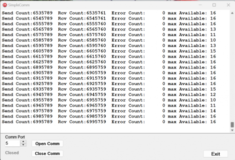
Here are a couple of screenshots showing about 6 million packets exchanged without error---but nothing else was happening except the data exchange and a statistics display once per second.

Screenshot_20230114_120315.pngScreenshot_20230114_120437.png
 
It just occurred to me that it may not be a good idea to directly connect the serial output of a T4.1 to an input on another T4.1 that may be powered off. Isn't that going to drain a lot of current from the serial output, as the default state for the output is 3.3V when there is no data being transmitted? I minimized the problem a bit by connecting both T4.1s to a serial hub that was unpowered until plugged in. My T4.1s seem OK so far, but you can bet that I would never try that with one of my T3.6's!!
 
It just occurred to me that it may not be a good idea to directly connect the serial output of a T4.1 to an input on another T4.1 that may be powered off. Isn't that going to drain a lot of current from the serial output, as the default state for the output is 3.3V when there is no data being transmitted? I minimized the problem a bit by connecting both T4.1s to a serial hub that was unpowered until plugged in. My T4.1s seem OK so far, but you can bet that I would never try that with one of my T3.6's!!

A 1k resistor in series would protect against destructive harm.
You can also use one and the same pin for UART Rx and Tx, in a half duplex mode. In the DMA_UART code that I shared this mode is enabled by giving the pin for RS485 style data direction a negative value on initialization. By default, when not transmitting, the pin is an input, so cannot be a parasitic power supply for the other possibly powered off Teensy.
But make sure that when transmitting it's push-pull and not open drain because 6Mbaud and open drain with a pullup will be stretching it too far.
Same bi-directional pin can also be used to interwire >2 Teensies. But the protocol needs a specific target address indicator, and only one Teensy would be the master that initiates traffic on that 1 wire bus. I think the OP needs a (one) Teensy master role assigned anyway for node synchronization.
 
I definitely agree with @mborgerson that synchronization and error checking are necessary for reliability. Here is an example using the SerialTransfer library, which handles packet creation, send, receive, and error checking, and runs on a single T41.

The Producer "task" uses SERIAL1, sends a data packet and waits for a response.
The Consumer "task" uses SERIAL3, waits for a data packet and sends a response.

Packet overhead is high for very short messages, such as the 4 x float the OP specified, so you can experiment with sending data less often (multiple samples per message) and with or without an IntervalTimer. With INTERVAL_TIMER = 0 and SAMPLES_PER_MSG = 1, the producer and consumer can exchange about 19000 samples per second, so the CPU usage for 10000/sec is about 50%. If SAMPLES_PER_MSG is increased to 10, about 33500 samples can be sent per second, reducing CPU usage to about 30%.

Code:
// Producer/Consumer via UART -- Joe Pasquariello -- 01/15/23

#include "SerialTransfer.h"
#include "IntervalTimer.h"

SerialTransfer Producer, Consumer;

IntervalTimer ProducerTimer;
volatile uint8_t producerTimerFlag = 0;

typedef struct {
  float a,b,c,d;
} DataStruct;

#define INTERVAL_TIMER	(1)	// set to 0 to loop as fast as possible 
#define SAMPLES_PER_MSG	(1)	// max = 15 for SerialTransfer

// no extra serial buffer required for SAMPLES_PER_MSG < 8
uint8_t producerTxBuffer[1024];
uint8_t consumerRxBuffer[1024];

void setup()
{
  Serial.begin( 115200 );
  while (!Serial && millis() < 2000) {}
  
  ProducerSetup();
  ConsumerSetup();
}

void loop()
{
  ProducerLoop();
  ConsumerLoop();
}

void producerTimerCallback( void )
{
  producerTimerFlag = 1;
}

void ProducerSetup()
{
  Serial1.begin( 6000000 );
  Serial1.addMemoryForWrite( producerTxBuffer, sizeof(producerTxBuffer) );
  Producer.begin( Serial1 );
  if (INTERVAL_TIMER) {
    // start IntervalTimer (10 kHz for 1 sample/msg, slower for more sample/msg)
    ProducerTimer.begin( producerTimerCallback, 100*SAMPLES_PER_MSG );
  }
}

void ProducerLoop()
{
  static int State = 0;
  static elapsedMillis rxTimeout = 0;
  static elapsedMillis display = 0;
  static uint32_t rxOkay=0, rxOkayPrev=0;
 
  if (State == 0 && (INTERVAL_TIMER == 0 || producerTimerFlag == 1)) {
    // PRODUCER TX (data)
    DataStruct data[SAMPLES_PER_MSG] = { { 1.0, 2.0, 3.0, 4.0 } };
    Producer.sendData( Producer.txObj( data ) );
    State = 1;
    rxTimeout = 0;
    producerTimerFlag = 0;
  }
  else if (State == 1) {
    // PRODUCER RX (Ack)
    if (rxTimeout >= 5)
      State = 0;
    else if (Producer.available()) {
      char Ack;
      uint16_t rxSize = Producer.rxObj( Ack );
      if (rxSize == sizeof(char))
        rxOkay += SAMPLES_PER_MSG;
      State = 0;
    }
  }
  
  if (display >= 1000) {
    display -= 1000;
    Serial.printf( "  Producer: %10u %10lu\n", rxOkay-rxOkayPrev, rxOkay );
    rxOkayPrev = rxOkay;
  }
}

void ConsumerSetup()
{
  Serial3.begin( 6000000 );
  Serial3.addMemoryForRead( consumerRxBuffer, sizeof(consumerRxBuffer) );
  Consumer.begin( Serial3 );
}

void ConsumerLoop()
{
  static elapsedMillis display = 0;
  static uint32_t rxOkay=0, rxOkayPrev=0;
  
  // CONSUMER RX (data)
  if (Consumer.available()) { 
    DataStruct data[SAMPLES_PER_MSG];
    uint16_t rxSize = Consumer.rxObj( data );
    if (rxSize==sizeof(DataStruct)*SAMPLES_PER_MSG) {
      rxOkay += SAMPLES_PER_MSG;
      // CONSUMER TX (Ack)
      char Ack;
      Consumer.sendData( Consumer.txObj( Ack ) );
    }
  }
  
  if (display >= 1000) {
    display -= 1000;
    Serial.printf( "  Consumer: %10lu %10lu\n", rxOkay-rxOkayPrev, rxOkay );
    rxOkayPrev = rxOkay;
  }
}
 
Necro-posting, because I am so grateful!

I've been struggling with a mysterious data transfer issue that had to do with wrapping the Serial7 port in a MIDI object (Arduino MIDI library).
It turns out that the MIDI acquisition slowed things down enough to cause failures.

I added two lines from post 2 above after instantiation of the MIDI objects:
uint8_t bigserialbuffer[16384];
Serial1.addMemoryForRead(&bigserialbuffer, sizeof(bigserialbuffer));
Adding the buffer made the issues go away.

I'll pare down the buffer size now, but this post made all of the difference.
Thanks to the contributors above!

BTW, how big is the input buffer on hardware serial by default?
What's this about a 4-byte FIFO in post 9 above?
 
BTW, how big is the input buffer on hardware serial by default?
What's this about a 4-byte FIFO in post 9 above?

There are two buffers for each direction for each uart, one in the physical hardware and a software buffer that is managed in the libraries.

The physical hardware buffers are 4 bytes long, as bytes are received they are automatically placed in this buffer.
Once the hardware buffer contains a certain number of bytes (from memory the default is 2) or after a timeout if less data is received than the threshold an interrupt is triggered and the teensy library copies the waiting data from the hardware to the software buffer. If the UART interrupt could be disabled for long periods of time or you have lots of higher priority interrupts then decreasing this threshold can help. It means more interrupts overall but also means the system can take longer to respond to a uart interrupt before data is lost.

Calls to Serial1.read will be reading data out of the software buffer, Serial1.avalible() tells you how many bytes are waiting in that buffer.
Increasing this software buffer as you have done can help if part of your loop() code sometimes takes a long time and so there can be long periods where your code doesn't read the data from the serial port buffer.

The transmit side is similar, there is a software managed buffer that writes go into. The uart interrupt is then used to transfer data from that software buffer to the physical 4 byte transmit fifo in the hardware. This means that as long as the software buffer has space writes are fast, once the buffer is full writing becomes painfully slow since it'll have to wait for the uart to send some of the data and free up space.

The default size for the software buffers is 64 bytes in each direction. This is a reasonable compromise between memory usage and risk of overflowing, 64 bytes at normal baud rates is a huge amount of time. If however you are receiving at a very high baud rate or are sending data that is bursty (say you want to write out a 1k block of data once per second) then increasing the relevant rx or tx buffer size can make a huge difference.
 
Thanks so much! The trouble I was having makes perfect sense now. And the solution is behaving well. I do have short bursts, transferring a file.
 
. . .

The default size for the software buffers is 64 bytes in each direction. This is a reasonable compromise between memory usage and risk of overflowing, 64 bytes at normal baud rates is a huge amount of time. If however you are receiving at a very high baud rate or are sending data that is bursty (say you want to write out a 1k block of data once per second) then increasing the relevant rx or tx buffer size can make a huge difference.
A 64-byte buffer was probably a good choice in the days before the T4.x. For T4 systems, perhaps 512 bytes would be a better choice. Any T4 program that can't spare a few KB for buffers is probably so large or uses so much memory for data that it may have problems with stack space. However, 512 bytes still might not be enough for the fast transfer of packets several KB in length. Better visibility for the AddMemoryForRead and AddMemoryForWrite functions is probably the best solution, as there are a lot of T3.X systems out there where setting larger buffers by default might be problematic. However that could be handled by adding some #ifdef T4_1 statements to the Hardware Serial driver. It might also be possible to add a subclass like the USBSerialBigBuffer subclass in the TeensyHost driver.

For all that I've complained about the sea of #ifdefs in some driver code, there are occasions where it makes sense to have drivers that have to handle different CPUs use code optimized for each CPU.

I've had to use the larger buffers regularly as I often communicate with UBLOX GPS systems at 230KBaud and Boson thermal cameras at 921KBaud. The high baud rates reduce the time it takes to send a command and get a response. Having buffers larger than the command or response means my code doesn't have to hang around waiting for a transmission to complete and a response to arrive.
 
If there was only one or two uarts 512 bytes would be fine. But there are 8 ports, two buffers per port that's 8k of RAM which is completely wasted for most applications. That's enough memory that you don't want to just throw it away to make life a little easier for a few people.
 
Back
Top