Reading buttons with 4067 multiplexer

stanm

New member
First time working with multiplexers. The goal is to read input from 16 buttons, but I'm struggling to figure out the wiring with a minimal single button setup. Don't think it's an issue of poor connections as I did have it half-working at one point -- the mux would read high after pressing and holding the button, but this was in a wiring configuration that didn't make much sense to me. The wiring in the attached image is how I have it now, and is closer to how it seems like it should be, but I'm very likely mistaken as button presses don't cause any change in the reads. Any ideas?

I'm using a Teensy 4.1 powered by external 5V (not USB), SparkFun CD74HC4067 mux breakout, and the MUX74HC4067 library.
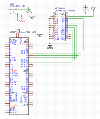
troubleshoot.PNG

Code:
#include "MUX74HC4067.h"

#define EN_PIN 21
#define S0_PIN 20
#define S1_PIN 19
#define S2_PIN 18
#define S3_PIN 17
#define SIG_PIN 16

MUX74HC4067 mux(EN_PIN, S0_PIN, S1_PIN, S2_PIN, S3_PIN);

void setup(void)
{
  ...
  mux.signalPin(SIG_PIN, INPUT, DIGITAL);
}

void loop(void)
{
  byte data;
  data = mux.read(0);
  Serial.println(data);
}
 
Last edited:
A circuit problem, probably. Can you check the pins on your circuit, they seem to differ from the datasheet actually:

https://www.sparkfun.com/datasheets/IC/cd74hc4067.pdf


24 is Vcc and 12 is GND on the datasheet. The pinout on your circuit diagram is different?! Although you're using a breakout board with the connections labelled,not numbered...
 
Here some addtional input.

  • In loop you are printing without any delay which will generate overrun issues on the serial monitor. Add some delay to your loop 1ms should be good.
  • You are pulling up your switch to 5V! Since the 4067 is a analog mulitplexer this 5V will apear at the SIG pin and finally at pin 16 of your Teensy. This may destroy this pin or the complete Teensy. Connect the resistor to 3.3V instead to prevent this.
    I recommend to do some simple test if pin 16 is still working. E.g., do a digitalRead on the pin and print the result while connecting it to 0V / 3.3V with a wire (don't forget the delay as mentioned above)
  • Although the newer versions of the 4067 are much faster than the old ones they still need some 100ns for switching the inputs, (especially with low VCC). On a quick check I didn't find any means in the library to guarantee the correct timing which probably is no problem at all for the slow AVR processors but might be for a Teensy.
    For your simple example this might be no issue but keep this in mind when you scan through your buttons later.
  • Generally, the 4067 interface is so simple that I wouldn't use a library at all. Just enable the chip by writing 0 to EN_PIN, write the channel number on pins S0-S3, wait 1us and read the value from the SIG pin.
    For your test this would mean (untested):
    Code:
    #include "Arduino.h"
    
    #define EN_PIN 21
    #define S0_PIN 20
    #define S1_PIN 19
    #define S2_PIN 18
    #define S3_PIN 17
    #define SIG_PIN 16
    
    void setup(void)
    {
        pinMode(EN_PIN, OUTPUT);
        pinMode(S0_PIN, OUTPUT);
        pinMode(S1_PIN, OUTPUT);
        pinMode(S2_PIN, OUTPUT);
        pinMode(S3_PIN, OUTPUT);
        pinMode(SIG_PIN, INPUT_PULLDOWN);
    
        digitalWriteFast(EN_PIN, LOW); // enable the chip
    
        digitalWriteFast(S0_PIN, LOW); // select channel 0
        digitalWriteFast(S1_PIN, LOW);
        digitalWriteFast(S2_PIN, LOW);
        digitalWriteFast(S3_PIN, LOW);
        delayMicroseconds(0); // not needed here since you never change the address but don't forget this when you rapidly change channels
    }
    
    void loop(void)
    {
        Serial.println(digitalReadFast(SIG_PIN)); 
        delay(100);
    }
 
Last edited:
Hey!

I would like to add a +1 to that "You don't need a library to set 3 or 4 bits to choose an address, wait a moment and read a pin".
Keep in mind, that those ICs need some time between you choosing the channel you want to read (aka set the bits on those pins) and being able to provide the data to the output pin. You should either look into the documentation of your chip or just add a few microseconds after you set the pins (like luni did but just with a number > 0). I am playing save with around 60microseconds on my 4051.
I cannot see any delay in the library you are using. My 4051 would not return the values I expect with that code.
 
As an aside, why not use something like this.
It handles all your keyboard scanning and only requires two pins (3 if you include interrupt).
 
I was able to figure it out this morning, thank you all for the suggestions.

I still had code in my setup function for initializing a large TFT display I'm using, including the following culprit:
Code:
Wire.setClock(400000);
Wire.begin();
The button reads perfectly after removing this. As I understand it, the Wire.begin() conflicts with my mux as the pins I'm using are also used for I2C? I think this was code from an example that set up the display's touchscreen capabilities, which I am not using. I admit this should have been the first thing to go when I started troubleshooting. This is what happens when you copy-paste examples you don't fully understand!

luni said:
You are pulling up your switch to 5V! Since the 4067 is a analog mulitplexer this 5V will apear at the SIG pin and finally at pin 16 of your Teensy. This may destroy this pin or the complete Teensy. Connect the resistor to 3.3V instead to prevent this.
I've corrected this, thank you.

luni said:
Generally, the 4067 interface is so simple that I wouldn't use a library at all.
Makes sense, I initially wasn't using a library but decided to pull one in to eliminate the possibility that I was interfacing with the mux incorrectly.

BriComp said:
As an aside, why not use something like this.
It handles all your keyboard scanning and only requires two pins (3 if you include interrupt).
This project will be using a row of 16 mechanical key switches, so it feels like the 4067 is appropriate. Each key will also have a corresponding LED, which I haven't yet thought through fully, but I'll likely use something like a TLC5940. Open to suggestions there.

Thanks again, all.
 
Last edited:
Hey!

I was in the same situation like you: Mechanical Keys and a LED for every key. How do I talk to them etc? I ended up using WS2812B (that cost around 7€ for 100pc if you order them from china. Did it on eBay. Takes some time to arrive, but never had issues with it).
They work great with 3.3V and all you need to do is provide them with power, connect them to one of the available Serial TX Pins and talk to them with the WS2812 Library, Paul wrote. I added a a spot for capacitors at every LED but it didn't make a difference, if I added them, so I did add one ever 8 LEDs to be save. I am using 69 of it and it works great! They fit unter MX Buttons, are doable to solder by hand... I used them in 2 music related projects already. You shouldn't design them to be too far into the Keys. The board of the sequencer is not the one I am using, because adding the Buttons and using them pressed hard on a few LEDs, that I soldered to deep down. Those that look out 1 mm are good placed. Second attempt went flawless.

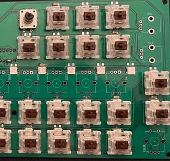
sequencer.jpg
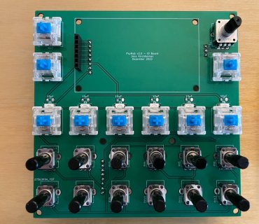
hub.jpg

All the MX Buttons (I think its 56 or something on the sequencer) are connected to 9 Multiplexer and its even easy to debounce them in code.
 
Back
Top