Following
These values aren't necessarily set in stone so a certain amount of flexibility is required
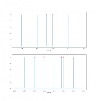
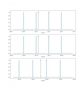
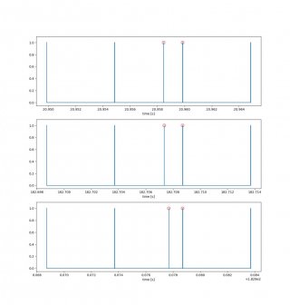
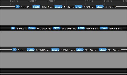
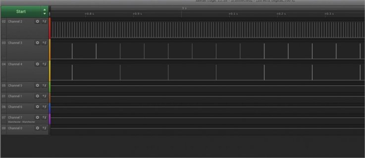
Overall this has been working fine but I am experiencing some unexpected deviation in the rising edges. I'm using a saleae logic pro 8 as oscilloscope and clock the following results after collecting data for 10 mins
I'm still analyzing but I think it seems pretty clear that the increase in std_dev comes from the standout f_max.
Note: I am working with interrupts so this definitely lends an element of complexity, but AFAIK, these interrupts are small and implemented "correctly". The interrupts are:
For keeping timing up to date
and for responding to the periodic timer interrupts:
Is there some overhead associated with using teensytimertool which I can get around?
I have the data in csv, but I'm having trouble attaching this. I can attach the code as well, but it's grown relatively long at this point, so not sure how much people want to comb through its entirety.
- https://forum.pjrc.com/threads/71506-Time-synchronization-and-triggering-sensors
- https://forum.pjrc.com/threads/71671-Augmenting-Teensy-millis-timing-with-external-RTC
These values aren't necessarily set in stone so a certain amount of flexibility is required
Overall this has been working fine but I am experiencing some unexpected deviation in the rising edges. I'm using a saleae logic pro 8 as oscilloscope and clock the following results after collecting data for 10 mins
- run 1
- 200 Hz => [f_max, f_mean, std_dev] = [200.006, 200.001 Hz, 66.801 ns]
- 20 Hz => [f_max, f_mean, std_dev] = [20, 20.0 Hz, 69.55 ns]
- 10 Hz => [f_max, f_mean, std_dev] = [10, 10.0 Hz, 80.643 ns]
- run 2
- 200 Hz => [f_max, f_mean, std_dev] = [990.805, 200.006 Hz, 19.808 us]
- 20 Hz => [f_max, f_mean, std_dev] = [116.118, 20.005 Hz, 635.732 us]
- 10 Hz => [f_max, f_mean, std_dev] = [115.529, 10.005 Hz, 1.836 ms]
I'm still analyzing but I think it seems pretty clear that the increase in std_dev comes from the standout f_max.
Note: I am working with interrupts so this definitely lends an element of complexity, but AFAIK, these interrupts are small and implemented "correctly". The interrupts are:
For keeping timing up to date
Code:
void setupInterrupt(const uint8_t & pin)
{
  pinMode(pin, INPUT_PULLUP);
  attachInterrupt(digitalPinToInterrupt(pin), fallingISR, FALLING);
}

elapsedMicros micros_from_second;
volatile uint32_t unix_seconds;
void fallingISR()
{
  micros_from_second = 0;
  unix_seconds++;
}
and for responding to the periodic timer interrupts:
Code:
inline void prepare_message(
const uint8_t & type, const uint32_t & seconds, const uint32_t & micros, const uint32_t & count,
uint8_t msg[])
{
msg[0] = type;
memcpy(&msg[1], &seconds, sizeof(seconds)); // 1->4
memcpy(&msg[5], µs, sizeof(micros)); // 5->8
memcpy(&msg[9], &count, sizeof(count)); // 9->12
}
inline void TriggerGenerator::PeriodicCallback()
{
  digitalWriteFast(pin_, HIGH);
  // REVIEW: need no interrupt?
  micros_ = micros_from_second;
  seconds_ = unix_seconds;
prepare_message(type_, seconds_, micros_, count_, msg);
Serial.write(msg, msg_size); // msg_size const is 13
++count_;
TriggerFallingEdge();
}
inline void TriggerGenerator::TriggerFallingEdge() { one_shot_timer_.trigger(width_); }Is there some overhead associated with using teensytimertool which I can get around?
I have the data in csv, but I'm having trouble attaching this. I can attach the code as well, but it's grown relatively long at this point, so not sure how much people want to comb through its entirety.


