Advice on graphical mouse/keyboard UI (T4.1 + TFT)

MrCanvas

Well-known member
Hi,

For reasons unknown I have started to recreate the old Notator/Creator sequencer software originally made for Atari. The intention is to run this on a T4.1 with a 5-7" TFT (yet to be selected). As I already made a couple of sequencer projects which can be reused this is so far mainly a UI project.

I despise touch control, so want to use a graphical mouse/keyboard UI (external peripherals on usb, no problem there). Having never worked with the concept of mouse cursors, I ran into many cases where it is difficult to draw the cursor and background cleanly without a full screen redraw (which is too slow). Just deleting at the last cursor position and redrawing at the new is sometimes ok but there are many cases where it is not. What is the best way to accomplish this? Are there libraries for controllers like RA8875 that support "overlay" in a suitable fashion?

Apart from the cursor, there are no elements that need to be updated frequently.

Here is an example from the original UI. It was usually run at 640x400 resolution on a monochrome monitor:
https://exxosforum.co.uk/atari/mirror/tamw/notator.htm

Any hints are welcome. Apologies for rambling.

Cheers, Daniel
 
Any hints are welcome.

Cheers, Daniel

@MrCanvas(Daniel):

I have used <this> 7" RA8875 800x480 TFT display from buydisplay.com with great success in several of my Teensy projects. It comes with a selectable resistive/capacitive touchscreen, but I believe that you can leave it off when selecting the options.

Here are the option selections that I am using:

Code:
         Display options (ER-TFTM070-5):
            Interface:               Pin Header Connection-4-wire SPI
            VDD:                     5.0V (can always change the jumper later to power from 3.3VDC)
            Touch Panel:             7" Capacitive Touch Panel with Controller
            MicroSD Card Interface:  Pin Header Connection (not useable - see display docs)
            Font Chip:               (none selected)

The library for it (which is automatically loaded with TeensyDuino) is very good. You can throw update commands to the display as fast as the Teensy can generate them, & the internal controller on the display parses & dispatches them asynchronously (no hold-off or waiting by the Teensy).

For your specific application, using the dual-layer capability would allow you to draw/undraw/redraw the cursor on one layer & everything else on the other layer. This is exactly what I am doing in the latest version of my TeensyMIDIPolySynth project.

Hope that helps . . .

Mark J Culross
KD5RXT
 
Thanks Mark, much appreciated! I had that one on my list of options so will go ahead and throw some more money at BuyDisplay.
 
Continuing on this adventure... First of all - the RA8875 display is great, and it has exactly the kind of features I was wishing for (layers etc). However after initial success I ran into an obstacle.

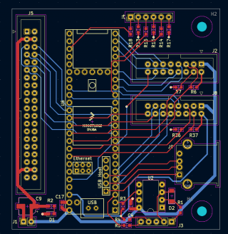
I first did an ugly breadboard solution which worked great from the start. Encouraged by this I made a simple adapter pcb for a T4.1 to be soldered on the display pin header (see picture below). Main goal was to keep the height down.

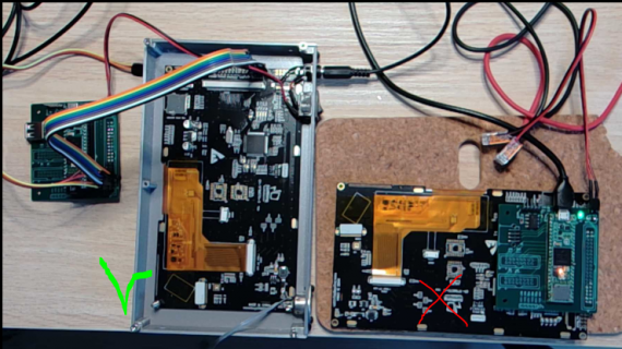
If I use this board as intended (i.e soldered to the display), the display stays dark. It looks like SPI is somewhat working as I get no errors during initialize. But the low current draw (150mA) suggests that at least the backlight is not coming on.

If I instead use the same pcb but connect the display pin-to-pin with 10-20cm breadboard wire, everything works perfectly fine.

Looking at old posts I see similar problems but I am not sure there is a workaround. I can always use a "wired" connection to the display but prefer not to. Any of the Teensyduino RA8875 examples can be used to reproduce.

Things I checked:
- wrong pinout, no
- bad ringing on SPI signals (possibly dampened by added wires) - no they seem ok and similar in both configurations
- difference in display power-on time, no
- running at lower SPI frequency, no change

Any suggestions?

pcb.PNG

d.PNG
 
At first glance everything looks OK. I only have experience with the RA8876, but I *think* the pinouts are the same. It's not really clear from your PCB image about the grounds. On my RA8876 PCB, I have grounded 1,2,13,31,39 and 40. Although it doesn't really explain why it works when you wire the panel using jumpers.
 
Thanks for checking. I have the same pins grounded on the pcb (there are 2 ground layers not shown above), looks like the pinout is the same.
 
Thanks for checking. I have the same pins grounded on the pcb (there are 2 ground layers not shown above), looks like the pinout is the same.

@MrCanvas (Daniel):

You probably found my earlier posts where I had almost the exact same experience with the RA8875: my wire-wrapped prototype worked flawlessly, but I could never get the first two versions of the PCB to ever work (at $200 per run of minimum order three PCBs, that was a very expensive failure !!). The ultimate solution (in my particular case) is still unbelievable to me.

A little background to set the stage: my TeensyMIDIPolySynth (TMPS) includes two Teensy processors, one T4.1 to run the RA8875 display & to take care of all MIDI interfaces (DIN, USB, USBhost), and one T4.0 to run the audio interface board. These two Teensy processors are interconnected by a bidirectional serial interface running at 500kbaud.

Being concerned about minimizing any noise coupling, especially into the audio chain, in my first two PCB versions, I placed a ground pour on both sides. The two ground pours were interconnected by periodically placed vias. Just like you described, I checked & double-checked the wiring against the pinout (all confirmed correct), I measured the SPI signals with my very nice Rigol scope (similar in both configurations), I tried adding delays in different places to see if it made any difference in the power-up sequence (none), and just like your attempts, I even tried running SPI at a slower frequency (no improvement).

After two failed PCB attempts (in the second one, I moved the T4.1 & T4.0 further apart, just in case the high-rate clocks to the audio interface were somehow negatively coupling into the display interface) & a $400 hole in my pocket with nothing to show for it, I decided that I'd make a third & final attempt with a fairly radical change: I eliminated both ground pours & I'm ecstatic to report that the third board has worked like a champ ever since !! I am more of a software person, but if I had to guess what was happening, I'd guess that the two ground pours may have been acting like a very large capacitor around one or more of the display signals & interfering with some critical timing requirement. Again, purely a non-scientific guess. With my limited hardware knowledge & experience, I would never have believed that eliminating a ground plane could contribute to a positive improvement !!

My wire-wrapped prototype was quite the disorganized rats nest of wires, so I really thought that cleaning it up into a PCB with a very carefully poured ground plane would improve things overall. And, the good news is that I still don't have any noise problems, so I'm a very happy TMPS camper !!

So, it sounds completely non-intuitive, but try eliminating your ground planes & see if that helps you as well. Hope that helps !! Good luck & have fun !!

Mark J Culross
KD5RXT
 
Thanks for sharing your story Mark. I did notice that you had a similar experience to mine, and I recognize the frustration when an ugly mess of cables work but a tidy pcb doesnt.

Ground planes are an interesting topic. I started designing pcb's only a couple of years ago and on recommendation from my E/E colleagues I spent a lot of time listening to Rick Hartley and Eric Bogatin (both are epic) and understanding their (somewhat different) recommendations on how approach signal integrity on a pcb. Just thinking carefully about uninterrupted return paths made a huge difference in other designs for me. Clearly, not so much in this case.

Luckily these pcb's are cheap so maybe I will redesign slightly.
 
Back
Top