Teensy 4.1 noisy/spurious digital output

mnissov

Well-known member
Debugging this has been troubling me a great deal now at this point. I've written a very basic script which polls in `loop()` to create a 200Hz square wave with 10us high time.

My logic analyzer (saleae logic pro 8) reports f_mean 200.000503 Hz with 3.27ns standard deviation for the first 40 seconds
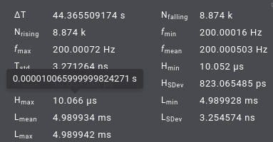
new_teensy_stats.png
after which this happens
new_teensy_window.png
zooming in on the spurious measurements reveals
new_teensy_window_zoomed.jpg

This has really been gnawing at me, I simply cannot fathom how this could be happening with such a basic script. Cables are short and far from external, powered devices. So I figure it's not an interference issue. Pins are soldered to the teensy so there should be any possibility for movement. Note also, logic analyzer sampling at 500 MS/s

Here is the code I ran, I didn't clean it for sake of not accidentally removing something which could somehow affect the performance in a surprising way.
Code:
#include <Arduino.h>

const uint8_t _pin_out_ = 2;
const uint8_t _pin_gnd_ = 1;

elapsedMicros g_rising_edge_timer;
elapsedMicros g_falling_edge_timer;
uint32_t g_rising_edge_cycles;
uint32_t g_falling_edge_cycles;

uint32_t threshold;
bool g_is_high{false};
uint32_t g_interval = 5000 * (F_CPU / 1000000);  // 5ms
uint32_t g_width = 10 * (F_CPU / 1000000);         // 10us
void setup()
{
  pinMode(_pin_gnd_, OUTPUT);
  digitalWriteFast(_pin_gnd_, LOW);
  pinMode(_pin_out_, OUTPUT);
  digitalWriteFast(_pin_out_, LOW);

  if (ARM_DWT_CYCCNT == ARM_DWT_CYCCNT) {    // Enable CPU Cycle Counter
    ARM_DEMCR |= ARM_DEMCR_TRCENA;           // enable debug/trace
    ARM_DWT_CTRL |= ARM_DWT_CTRL_CYCCNTENA;  // enable cycle counter
  }

  Serial.begin(9600);
  while (!Serial) {
  }
  g_rising_edge_timer = 0;
  g_falling_edge_timer = 0;
  g_rising_edge_cycles = ARM_DWT_CYCCNT;
}

void loop()
{
  // if (g_rising_edge_timer >= g_interval) {
  //   digitalWriteFast(_pin_out_, HIGH);
  //   g_rising_edge_timer -= g_interval;
  //   g_falling_edge_timer = 0;
  //   // threshold = g_falling_edge_timer + g_width;
  //   g_is_high = true;
  // }

  // if (g_is_high && (g_falling_edge_timer >= g_width)) {
  //   // if (g_is_high && (g_falling_edge_timer >= threshold)) {
  //   digitalWriteFast(_pin_out_, LOW);
  //   g_is_high = false;
  // }
  if (ARM_DWT_CYCCNT - g_rising_edge_cycles >= g_interval) {
    digitalWriteFast(_pin_out_, HIGH);
    g_is_high = true;
    g_rising_edge_cycles = ARM_DWT_CYCCNT;
    g_falling_edge_cycles = g_rising_edge_cycles;
  }

  if (g_is_high) {
    if (ARM_DWT_CYCCNT - g_falling_edge_cycles >= g_width) {
      digitalWriteFast(_pin_out_, LOW);
      g_is_high = false;
    }
  }
}
 
Last edited:
Tried your code a couple of times, 200s measurement interval each but I can not see any spurious pulses. L_min = 4.991ms L_max=4.991ms. In principle my LA could be too slow (24MHz) to see any of the the short spurious pulses so the measurement should be taken with a grain of salt.
 
I set my logic analyzer to 25 MS/s (I couldn't choose 24MS/s) and got this
25MSps_window.jpg
If I zoom in it's 40ns this time, but still happening
25MSps_window_zoomed.png

Note this happened after recording for approximately 3s.

It continues happening sporadically for the remainder (recorded 30 mins by accident) and the 4 I've explicitly zoomed in and observed were all 40ns, placed randomly between two normal rising edges.
 
No chance to reproduce this here.

I also connected pin_out to pin3 and attached a pin interrupt to pin3 to measure the time between two pulses. No deviation from the expected value detected.


Code:
#include <Arduino.h>

const uint8_t _pin_out_ = 2;
const uint8_t _pin_gnd_ = 1;

elapsedMicros g_rising_edge_timer;
elapsedMicros g_falling_edge_timer;
uint32_t g_rising_edge_cycles;
uint32_t g_falling_edge_cycles;

uint32_t threshold;
bool g_is_high{false};
uint32_t g_interval = 5000 * (F_CPU / 1000000); // 5ms
uint32_t g_width    = 10 * (F_CPU / 1000000);   // 10us

elapsedMicros timer = 0;
void detectGlitch()
{
    if (timer > 5005 || timer < 4995)
    {
        Serial.printf("gotcha %d\n", (unsigned)timer);
    }
    timer = 0;
}

void setup()
{
    pinMode(_pin_gnd_, OUTPUT);
    digitalWriteFast(_pin_gnd_, LOW);
    pinMode(_pin_out_, OUTPUT);
    digitalWriteFast(_pin_out_, LOW);

    if (ARM_DWT_CYCCNT == ARM_DWT_CYCCNT)
    {                                           // Enable CPU Cycle Counter
        ARM_DEMCR |= ARM_DEMCR_TRCENA;          // enable debug/trace
        ARM_DWT_CTRL |= ARM_DWT_CTRL_CYCCNTENA; // enable cycle counter
    }

    pinMode(3, INPUT_PULLUP);
    attachInterrupt(3, detectGlitch, RISING);

    while (!Serial) {}
    g_rising_edge_timer  = 0;
    g_falling_edge_timer = 0;
    g_rising_edge_cycles = ARM_DWT_CYCCNT;
}

void loop()
{
    if (ARM_DWT_CYCCNT - g_rising_edge_cycles >= g_interval)
    {
        digitalWriteFast(_pin_out_, HIGH);
        g_is_high             = true;
        g_rising_edge_cycles  = ARM_DWT_CYCCNT;
        g_falling_edge_cycles = g_rising_edge_cycles;
        //timer                 = 0;
    }

    if (g_is_high)
    {
        if (ARM_DWT_CYCCNT - g_falling_edge_cycles >= g_width)
        {
            digitalWriteFast(_pin_out_, LOW);
            g_is_high = false;
        }
    }
}
 
Here is a simpler program that produces 200 Hz signal with 10 us high time.

Code:
#include <Arduino.h>

const uint8_t _pin_out_ = 2;

uint32_t period  = 5000 * (F_CPU / 1000000); // 5000 us
uint32_t hi_time = 10 * (F_CPU / 1000000);   //   10 us
uint32_t lo_time = period - hi_time;         // 4990 us 

volatile bool hi;
volatile uint32_t now, start;

void setup()
{
  Serial.begin(9600);
  while (!Serial) {}
  Serial.println( "Starting..." );
  
  pinMode(_pin_out_, OUTPUT);
  digitalWriteFast(_pin_out_, LOW);
  start = ARM_DWT_CYCCNT;
}

void loop()
{
  now = ARM_DWT_CYCCNT;
  if (!hi) {
    if (now - start >= lo_time) {
      digitalWriteFast(_pin_out_, HIGH);
      hi = true;
      start = now;
    }
  }
  else {
    if (now - start >= hi_time) {
      digitalWriteFast(_pin_out_, LOW);
      hi = false;
      start = now;
    }
  }
}
 
@luni so perhaps it's my logic analyzer? I've tried with 2 separate teensy's so it shouldn't be a busted MCU.

Which logic analyzer are you using?
 
I haven't tried grounded the unused inputs, they're just hanging. I'll give that a try though.

Will be disappointing otherwise, I think this one is supposed to be relatively "fancy". Whatever that means. Would make sense if it was the logic analyzer though, can't explain whythis would happen otherwise.

I'm using Logic Pro 8 and getting the correct results with my sketch.

EDIT: I'm getting the correct result with your sketch, too. Sampling igital signal at 500 Msps, trigger on rising edge.
 
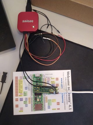
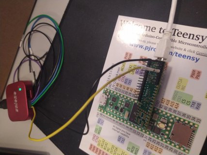
How different is my physical setup from yours?
setup.jpg

I figure this has very limited possibility for interference as I've tried to route cables separately from one another, but at this point I really don't know.

Note, now I've tried to switch out the cable harness, switching to the other set of ports, and connecting the unused inputs to ground in separate experiments and all result in the same behavior. Think I'll try and find another logic analyzer and contact saleae because this seems to be very isolated to me.
 
Not entirely sure I understand, what do you mean by real ground? Isn't digital out low connected to the USB cable ground?
 
Not entirely sure I understand, what do you mean by real ground? Isn't digital out low connected to the USB cable ground?

looking at the image it seems the wires are on pins 1 and 2 with no connection to a gnd pin for reference. GND is on the corner before pin 0.
 
I set pin 1 to LOW with digitalWriteFast(_pin_gnd_, LOW);. Is this not sufficient as a ground source?

Maybe not in the case of signal quality?

Edit: Same thing happens regardless of whether I'm connected to pin 1 with digitalWriteFast(1, LOW) or connected to the pin labeled "gnd"
 
I set pin 1 to LOW with digitalWriteFast(_pin_gnd_, LOW);. Is this not sufficient as a ground source

That's a lot better than depending on GND connection around a huge loop up one USB cable, through wiring inside your PC, and then back down the other USB cable.

But it's still considered poor practice compared to actually connecting GND to GND, where the GND wire closely follows the signal path.

Your Saleae logic analyzer has 8 signals and 8 GND pins, one GND pin directly underneath each signal pin, for a good reason....

Okay I see, thanks for the explanation. I'll try again and see what happens.


Note I attached a sensor to the output and it demonstrated weird behavior in the same region as one of these pulses. So it seems as though something may actually be happening here. Not sure why it's only affecting me however.


Tried again: Same behavior occurring very quickly after starting
zoomed.jpg
Cables connected as recommended
setup.jpg

Edit: same thing also happens with the script from p#5
zoomed.png


Edit2: This is with the arduino 2.0.3 apppimage and teensy loader 1.57
 
Last edited:
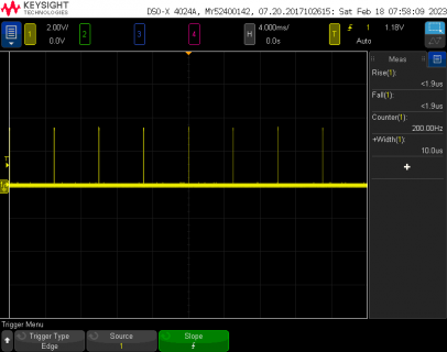
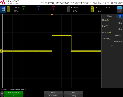
I tried the code from msg #5 on a Teensy 4.1 with my oscilloscope watching pin 2.

file1.png

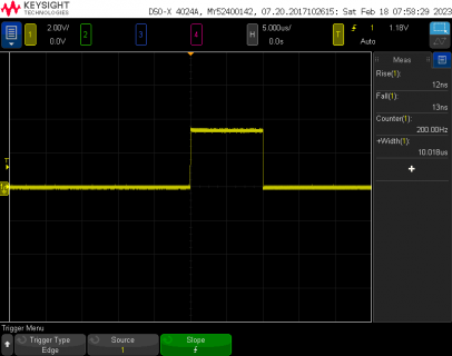
Here's a zoom in to just the pulse.

file2.png

I put my scope into display persistence mode, so if the waveform changes the anomalous image will remain on the screen together with all other captures. Here's a result after running for a couple minutes.

file3.png

Looks like the pulse really is the same every time, or at least so similar that variation can't be easily seen at this scale.
 
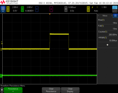
Tried again with the original code on msg #1. Connect scope to pins 1 and 2. Here's the result after a few minutes of updates in persistence mode. Can't see any significant variation in the waveform.

file4.png
 
Ok, I'm looking at this closer (quite literally) because I'm just not willing to leave this at a simple "tried it, can't reproduce problem".

The first bad waveform on msg #16 appears to have a total time of 300 ns, and the second one appears to be about 1/3 of that. My oscilloscope sreenshots are 50000 ns total time, because I just ran the program and adjusted the settings to see the waveform.

I had set my scope to bandwidth limit mode. Actually it was already in that mode, as I almost always leave it in that mode, because it appropriate for quick measurements of relatively low bandwidth stuff. But this is looking at little pulses. My best guess from the image is 4 wider pulses look like 5 ns wide and the 3 smaller ones look like 2.5 ns. To really look at such short pulses, we need the scope's full 200 MHz bandwidth (or ideally even more, but 200 MHz is the oscilloscope I have...)

Here comes a look at 200 ns time scale, and some practical info about how to make these higher bandwidth measurements. For that part I'm going to have to get my camera....
 
It happens not so often, but it's quite repetitively a burst of rising edges between two normally spaces rising edges, as in https://forum.pjrc.com/attachment.php?attachmentid=30414&d=1676654125.

Honestly, I am at a loss for what's wrong with my setup. ..... I just have no clue what could be left at this point.

It's almost certainly a high speed signal quality problem. I will show you. But to really explain this requires photos, and more work to do than the quick low-effort measurements I made in msg #17, #18, #19. Maybe I'll later write a blog article about this (maybe) because it really is a difficult problem that's almost impossible to really see and understand if you're working only with a logic analyzer.

I'm running a several minute display persistence test now with the higher-effort setup. Just shot some photos. These macro shots are always a bit tricky. Going to make sure I got a good photo, because I'm not eager to have to set this test up again.

Details coming, just a few minutes....
 
Thanks, I really appreciate the help.

The peaks for me if I measure at full speed (500MHz) will come as 5 or 6 peaks with max 8ns width, something in this range. The signal itself is relatively consistent in this form. In another comparison above I attempted sampling lower (25MHz) to compare with @luni, this resulted in one HIGH lasting about 40ns.

Just to say I have been able to capture what I believe to be the same phenomenon with lower sampling rate.

Edit:
Just saw this message
It's almost certainly a high speed signal quality problem. I will show you. But to really explain this requires photos, and more work to do than the quick low-effort measurements I made in msg #17, #18, #19. Maybe I'll later write a blog article about this (maybe) because it really is a difficult problem that's almost impossible to really see and understand if you're working only with a logic analyzer.

Really appreciate it because it's been frustrating to work through. What do you use aside from a logic analyzer to debug this? Also you say it's a high speed signal quality problem, is 200 Hz really so "high speed" for the teensy that one should expect problems like this? I ask only because I want to align my expectations properly.
 
One of the issues of using a logic analyzer is they give no information on signal integrity, whereas a reasonably capable 'scope with x10 probe may instantly diagnose issues like this. Perhaps crosstalk, ground-bounce, missing ground connection, noise interference, damaged pin - most of these are very visible on a 'scope trace.

Even worse when a signal has integrity issues different LA's may see different symptoms.

To me LA's come into their own with snooping on parallel busses, but there's still no substitute for a check with a 'scope for integrity issues.
 
Before I get into measurements, I need to say I still haven't managed to really reproduce anything that closely fits what you're seeing. So high speed effects may not be the entire story. But this message is about challenges measuring high speed signals.

All the measurements in this message have horizontal scale total time of 200 ns (or approx 200 ns where I tried to overlay your logic analyzer waveform onto the oscilloscope screenshot).

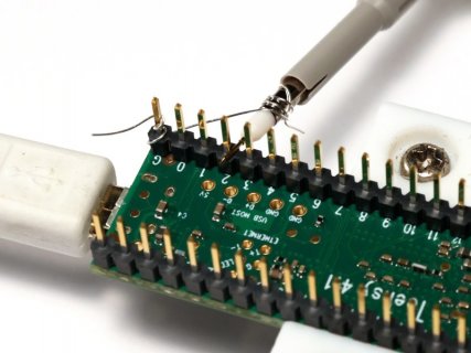
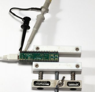
First, I measured with probe touching pin 2 and a small piece of wire directly from the probe tip to the nearby GND pin on Teensy 4.1. My scope has a spec of 200 MHz bandwidth, but I've long suspected they actually shipped about 300 MHz. The passive probes are rated for 700 MHz.

testsetup1.jpg

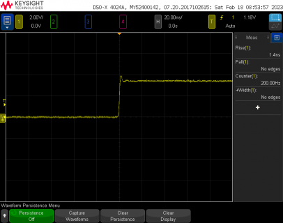
Here is the waveform my scope sees on pin 2.

file5.png

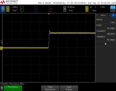
Here is a run for about 10 minutes with display persistence. The fat glow around the waveform is the scope's noise accumulated over 10 minutes. Higher bandwidth means more background noise. But like the other persistence tests, the important point is we're not seeing anything else in the picture. If little 5 ns or 2.5 ns pulses were happening, my scope would certainly pick them up and render them onto this display persistence image.

file6.png

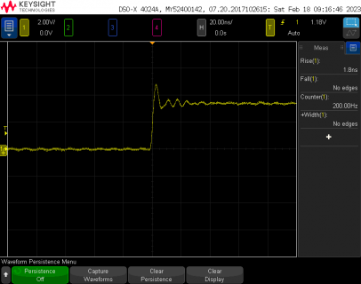
The reason I almost always leave my scope in bandwidth limit mode is because the scope probe rated to 700 MHz really isn't good for more than about 30-40 MHz with the extremely convenient ground clip (this clip is not original from Keysight... I spliced on the Pomona Minigrabber).

testsetup2.jpg

Here is the result with the exact same test using the ground clip. You can see it adds quite a lot of overshoot and ringing.

file7.png

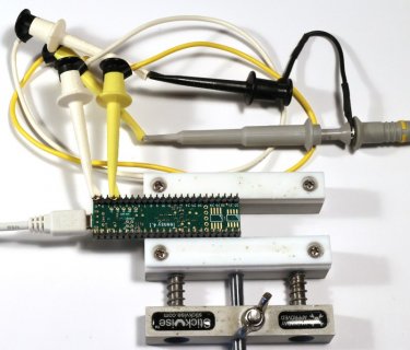
Now here is a third test where I added 2 clip leads (you can probably see I'm a big fan of Pomona Minigrabber). The idea was to try to see the difference extra wire length similar to the logic analyzer leads might make.

testsetup3.jpg

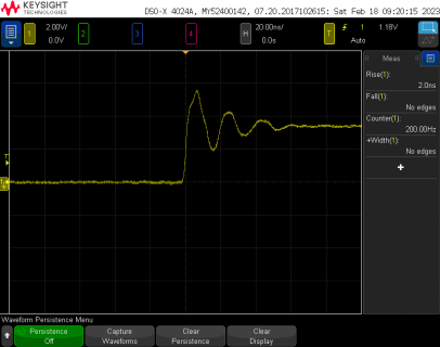
Here's what my scope sees with the extra wires added.

file8.png

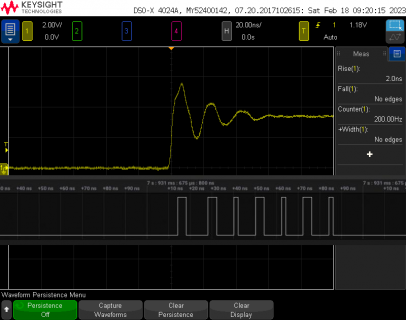
Now this isn't a nice match to the problem you're seeing. Your waveform started low and remains low after the pulses. So it could be some completely different problem. But look at the timing of the ringing due to the wire length matches up to the pulses your logic analyzer sees.

file9.png

So at this point, I'd say the true nature of the problem is still quite mysterious, mainly because your waveform starts low and ends low. The ringing effect would start low and end high, or start high and end low if you caught the undershoot and ringing from the falling edge.

Unfortunately, the 2 take-away messages are rather unpleasant.

1: Logic analyzers turn ugly analog problems into pristine-looking digital pulses. It's too easy to think the problem must be something digital like software.

2: Tiny pulses under 10 ns are the realm of high bandwidth measurements where even a few inches of ground clip wire adds substantial overshoot and ringing.
 
Back
Top