Expected levels from LINE OUT on Rev D audio adapter

kd5rxt-mark

Well-known member
I've recently gotten the PCB version of my latest TeensyMIDIPolySynth to work (woohoo !!). I've built out two copies for myself & a buddy to put them thru the paces in an attempt to rattle out any latent bugs. We've noticed on both of our setups that the LINE OUT signal levels are in the hundred millivolts range, whereas the audio design tool info on the SGTL5000 indicates that it should be in the 1-3Vpp range. Currently, my wife & I are making our way down the road (she's driving & I have access to only my phone at the moment, not to my laptop), so I will have to post some simple code & audio tool design info later. I thought I'd put the initial question out now to see if we should be expecting volts level or millivolts level outputs from the SGTL5000 ??

Thanks,

Mark J Culross
KD5RXT
 
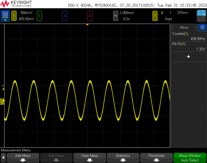
Documentation says default setting should be 1.29V peak-to-peak.

Tried this program just now on a Teensy 4.1 with Rev D2 audio shield

Code:
#include <Audio.h>

// GUItool: begin automatically generated code
AudioSynthWaveform       waveform1;      //xy=110,75
AudioOutputI2S           i2s_1;          //xy=303,78
AudioConnection          patchCord1(waveform1, 0, i2s_1, 0);
AudioConnection          patchCord2(waveform1, 0, i2s_1, 1);
AudioControlSGTL5000     sgtl5000_1;     //xy=302,184
// GUItool: end automatically generated code

void setup() {
  AudioMemory(15);
  waveform1.begin(WAVEFORM_SINE);
  waveform1.frequency(440);
  waveform1.amplitude(0.999);
  sgtl5000_1.enable();
}

void loop() {
}

My scope is measuring 1.32V peak-to-peak

file.png

This is for a waveform at 1.0 amplitude, where any more and you're clipping.

Also remember if you use a multimeter in AC voltage mode, it will measure RMS which is 2.828 times less than peak-to-peak, for a sine wave, and even less for most waveforms with musically pleasing sound.
 
Documentation says default setting should be 1.29V peak-to-peak.

My scope is measuring 1.32V peak-to-peak

This is for a waveform at 1.0 amplitude, where any more and you're clipping.

@Paul:

Thanks !! You beat me to the punch !! I was literally going to do the exact same simple code test & measure the output on that when we got back to our son's house. My buddy (also testing a second hardware copy of my TeensyMIDIPolySynth: TMPS) & I are both measuring the LINE OUT levels with o-scopes, so we should be able to see the same results as you.

In my TeensyMIDIPolySynth, there are a very large number of audio components (waveform generators, filters, envelopes, mixers, etc.) with quite the complicated collection of interconnects. In that setup, the individual waveform generator inputs to the 4-input mixers are each limited to a maximum of 0.25 such that the total output mix should never exceed 1.0 total.

I will not be able to do any testing this evening (visiting with local family), but I will take your test sketch & load it into a simple T4.0 + audio adapter combo (separate from the TMPS) tomorrow & measure the output in the same way that you did. I fully expect to get the same results.

The updated TMPS hardware includes one Teensy 4.1 running the 7" 800x480 RA8875 touchscreen display & one Teensy 4.0 running the audio adapter. with the two of them communicating over a shared 500kbps serial channel. After testing the simple standalone combo, I'll then reprogram just the T4.0 running the audio adapter on my TMPS & test that, then finally I'll re-test the actual TMPS with everything programmed with my current firmware sketches. The results from each of those tests should help to narrow down if the problem is related to my actual TMPS hardware, or something else that I'm doing wrong.

Thanks again for your answer & I'll let you know what I find.

Mark J Culross
KD5RXT
 
Last edited:
@Paul:

1) running your test sketch on a standalone T4.0 + audio adapter results in 1.3Vpp waveform as expected [ standalone hardware is good ]
2) modifying your test sketch to use a modulated waveform generator (as I do in TMPS), no change in hardware results in 1.3Vpp waveform as expected [ standalone hardware and software are good ]
3) running your test sketch using a mod waveform generator on the TMPS T4.0 + TMPS audio adapter results in 1.3Vpp waveform as expected [ TMPS hardware is good ]
4) running a shaved down version the TMPS audio sketch to include just the mod waveform generator & all subsequent mixers, executing on the TMPS T4.0 + audio adapter results in 60mVpp waveform [ TMPS software is bad ]

Identified problem: there are a string of six mixers that any VCO waveform passes thru on its way to the I2S output. Three of these mixers are set to a gain of 1.0 (pass-thru), but two of the remaining mixers are set to a gain of 0.25 (to allow up to four waveforms to all be mixed together without distorting thru the mixer), & the final mixer is set to a gain of 0.66 (who knows why !?!?!), so the mixer chain has an overall gain of 1/12, which results in a final output waveform amplitude of 1300mv/12, or roughly 100mVpp !!

Now, I'll need to go thru the mixer settings & find some way to ensure that the mix of waveforms is always as large in amplitude as possible, but still never exceeding 1.0 . . . I've got some work to do.

Paul: Thanks again for your initial confirming reply. The good news is that I have neither damaged my audio adapters, nor have I completely missed an audio adapter setting somewhere. As usual, a problem always makes complete sense, once the actual cause is determined !!

As always, I really appreciate everything that you do with & for the Teensy community, & in this case, specifically the capabilities built into & provided by the Teensy audio library !!

Mark J Culross
KD5RXT
 
To close the loop, I have re-balanced all of the mixers in the audio chain of my TMPS project, and I am now getting full-amplitude signals from the LINE OUT on the SGTL5000 audio adapter.

Working solution: For the mixers fed by the base-level waveform generators, it is easy to simply sum the slider level settings (0.00 to 1.0) for each of the waveforms. If that resulting sum is less than 1.0, then the input level settings sent to the mixer mixing the full-size outputs from the waveform generators are unchanged. However, if the sum exceeds 1.0, then the slider level settings are divided by that sum before being sent as input level settings sent to the mixer mixing the full-size outputs from the waveform generators, thus proportionally scaling the mixer input settings such that the summed output from the mixer does not exceed 1.0. This approach works very well.

For other mixers on down the chain, some of them are used as selective on/off control (e.g. the mixer that selects from among the unfiltered output, low-pass filtered output, band-pass filtered output, & high-pass filtered output from a filter object will have only one input level set to 1.0, corresponding to the desired selected filter output, and the remaining three input levels set to 0.0 to not use the other three filter outputs). These "selector" mixers & their settings were not changed. The remaining mixers in the audio chain sum the outputs from several earlier mixers & the exact level(s) of these outputs, now as inputs into the downstream mixer are not as easy to determine. For these, I used the universal "set each input level to 0.25, & therefore the sum of all of them will never exceed 1.0 in any given mixer" rule.

Unfortunately, this blind application of the "1/4 rule" still has the cascading effect of diminishing the overall signal level thru the entire audio chain (the real crux of the problem...it's a software problem !!). To address this, I added an amplifier object as the final component in the audio chain, with a gain setting ranging from 1.0 to 32.0. I also added a peak detector on the output from the amplifier, so I can detect when the signal is potentially clipping (theoretically, it would be when the output signal level exceeded 1.0, but since it's not possible for anything to actually exceed 1.0, I set the detected clipping level to 0.9). This works exceedingly well & I am now very happy with the ability to provide a full-amplitude signal of 3.2Vpp out from my TMPS on the LINE OUT interface !!

Thanks again to Paul for your replies & thanks especially for the awesome capability provided by the audio library !!

Mark J Culross
KD5RXT

P.S. When I get the final version of my TMPS PCB designed, fabricated, and populated (I need to add additional external hardware: e.g. circuitry to monitor the rechargeable battery level, a power switch (can't believe that I forget this in the original PCB !!), additional LINE OUT pins to allow an o-scope monitor connection in parallel with the 1/8 stereo audio jack, & an on-board power disconnect jumper to allow programming without worrying about USB power battling on-board power (without cutting the VIN/USB trace on the Teensy), etc.), I'll do my best to publish the project for others to enjoy & potentially build. MJC
 
Back
Top