Encoder too fast for Arduino? Would Teensy 4.0 help?

sathyas

Member
I have an Arduino Mega that I am currently using for reading encoder values and plan to perform velocity control for motors. I am using the following components: motor, gearbox, encoder.

I am using the basic example from the Encoder.h library and changed the loop() function to print the encoder value every 100ms. The interrupt pins (2,3) are being used.

The encoder has 1024*4*80 = 327680 counts per revolution due to the very high gear ratio of the gearbox. To get the desired robot speed, I would like to move the motors at 2 rev/s which is 655360 counts/sec. I am aware that this value is extremely (and unnecessarily) large but I already have these encoders and would like to use them if possible. (Worst case I will get an absolute encoder for the output shaft)

When turning the wheel by hand slowly the counts are relatively accurate, but when turning the wheel faster it seems like the Arduino Mega is unable to keep up with the interrupts (I think).

Would switching to a Teensy 4.0 resolve this problem? How many encoder counts per second could a Teensy reasonably handle? I plan to add a bit more code to the basic example for serial writing encoder values and performing PID for velocity control
 
I have run EncoderTool up to 400 KHz. I think beyond that you should look into the HW encoders in the post above.

I was able to use 64 bit counters for EncoderTool which meant I didn't need to deal with roll overs, at least in any practical time sense. Used EncoderTool to read a 4096 PPR rotary encoder on my lathe spindle. It is part of my Teensy based Electronic Lead Screw for my metal lathe.
 
The program below produces a simulated quadrature encoder output on pins 2/3 and uses the QuadEncoder library to count on pins 0/1. This works at frequencies up to 18.75 MHz (150 MHz / 8), which produces 75 million quadrature counts per second. I suspect the quadrature counting will work at higher frequencies, but 18.75 MHz is the highest we can simulate with this method.

EDIT: this is over 100 times the frequency required by the OP.

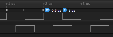
The program sets up 50% duty cycle PWM on pins 2 and 3, then manipulates the flexPWM registers to shift (delay) the pin 3 square wave by 90 deg (25%) relative to pin 2. These pins were chosen because they are channels A/B of the same FlexPWM (4) and submodule (2). The image below shows the result for a 1-MHz square wave. The maximum value of 18.75 MHz implies a high time of 8 clock cycles at 150 MHz, so at this frequency phase B is shifted from phase A by just 2 clock cycles, and I think that's as low as it can go.

The encoder count is read from the callback of an IntervalTimer to get a precise 1-second total count. For positive count, jumper 2-0 and 3-1. For negative count, jump 2-1 and 3-0.

Note that QuadEncoder has many features, but if all you want to do is count pulses from an IntervalTimer ISR, you only need the minimal configuration calls shown in setup().

T4_PWM_Shifted.png

Program output at 18.75 MHz

Code:
PWM frequency = 18750000 Hz
PWM high time = 4 clocks
         1    75000000
         2    75000000
         3    75000000
         4    75000000
         5    75000000

Code:
#include <Arduino.h>
#include <QuadEncoder.h>

const int pwmFreq = 18'750'000; // 18'750'000;
const int pwmRes  = 8;
const int pwmDuty = (1<<pwmRes) / 2;	// 50% duty cycle

const int pinA = 2;	// pin 2 = flexpwm 4, submodule 2, channel A
const int pinB = 3;	// pin 3 = flexpwm 4, submodule 2, channel B

QuadEncoder Enc(1, 0, 1); // QuadEncoder 1 of 4 w/ phases A/B on pins 0/1

IntervalTimer timer;

uint32_t encNow=0, encPrev=0;

void timer_callback()
{
  encNow = Enc.read();
}

void setup()
{
  Serial.begin( 115200 );
  while (!Serial && millis() < 2000) {}
  
  // initialize QuadEncoder
  Enc.setInitConfig();
  Enc.init();  

  // toggle LED to confirm program is running
  pinMode( LED_BUILTIN, OUTPUT );

  // set PWM resolution (bits)
  analogWriteResolution( pwmRes );

  // set duty cycle to 0 for both channels to allow trigger on first rising edge
  analogWrite( pinA, 0 );
  analogWrite( pinB, 0 );
  
  // set frequency for both channels
  analogWriteFrequency( pinA, pwmFreq );

  // set duty cycle to 50% for both channels
  analogWrite( pinA, pwmDuty );
  analogWrite( pinB, pwmDuty );

  // pins 2 and 3 are channels A and B of FlexPWM 4, submodule 2
  IMXRT_FLEXPWM_t *p = &IMXRT_FLEXPWM4;
  uint8_t submodule = 2;

  // shift PWM phase B to lag phase A by 90 deg
  p->MCTRL |= FLEXPWM_MCTRL_CLDOK(1<<submodule);  // do this before changes
  uint32_t hightime = p->SM[submodule].VAL3;      // use hightime already set
  p->SM[submodule].VAL2 = 0;                      // phase A rising edge
  p->SM[submodule].VAL3 = hightime;               // phase A falling edge
  p->SM[submodule].VAL4 = hightime/2;             // phase B rising edge
  p->SM[submodule].VAL5 = 3*hightime/2;           // phase B falling edge
  p->MCTRL |= FLEXPWM_MCTRL_LDOK(1<<submodule);   // do this after changes
  
  // read the encoder count every 1 second
  timer.begin( timer_callback, 1000000 );
  
  Serial.printf( "PWM frequency = %1lu Hz\n", pwmFreq );
  Serial.printf( "PWM high time = %1lu clocks\n", hightime );  
}

uint32_t seconds;
int32_t encDelta;  // Delta must be SIGNED (now/prev are UNSIGNED)

void loop()
{
  if (encNow != encPrev) {
    int32_t encDelta = encNow - encPrev;
    encPrev = encNow;
    digitalToggleFast( LED_BUILTIN );
    if (seconds > 0)
      Serial.printf( "%10lu  %10ld\n", seconds, encDelta );
    seconds++;
  }
}
 
Last edited:
Back
Top