Teensyduino 4.1 updating an e-ink display from duinotech

Hamish_Pye

New member
Hey there,

So essentially I'm attempting to connect my teensyduino 4.1 to a 1.54" E-ink display module and have run into problems. I managed to get this working on the teenyduino 3.5 however now that the pins are different I'm running into difficulty. I believe it has something to do with my pin connections and set up which I've mentioned below. Any help would be amazing thank you :)

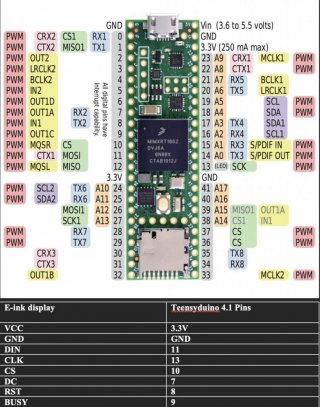
Pins from Eink are connected to the following pins from the teensyduino:

RST - 8
DC - 7
CS - 10
Busy - 9
CLK - 13
DIN - 11

I am also using :

https://github.com/waveshare/e-Paper/tree/master/Arduino/epd1in54

Any help would be very much appreciated!
 
Last edited:
Any help would be very much appreciated!

@Hamish_Pye:

Thanks for the library link . . . that's a useful start. Please post your sketch as well (make sure to enclose it in CODE tags - use the "#" button above the text composition area where you create your post) so we can take a look at what library calls you are making. Also, post a picture of your wiring if possible. And finally, do you have a link to the actual e-ink display that you are using ??

Mark J Culross
KD5RXT
 
@kd5rxt-mark

Sorry about that! I'm rather new to posting on this.

The module that I'm using is:

https://www.jaycar.com.au/duinotech-1-54-inch-monochrome-e-ink-display-module/p/XC3747

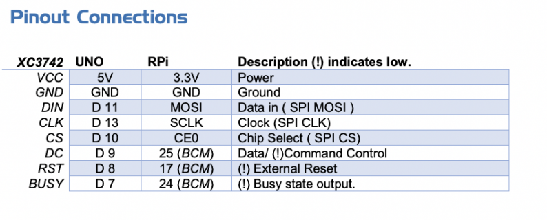
Alongside this, they supply the code attached in the initial post and pinout connections for if an Arduino Uno was used which I'll insert below.

Screen Shot 2023-02-24 at 1.00.22 am.png

In the epdif.h file the pins are assigned and at the moment my configuration for them while using the teensyduino 4.1 are as follows:

#include <Arduino.h>

// Pin definition
#define RST_PIN 8
#define DC_PIN 9
#define CS_PIN 10
#define BUSY_PIN 11

I guess my main question would be do these pins work ? However, as it doesn't work at the moment when feasibly it makes sense to me, I'm at a slight loss.

I have also attached what the pins from the teensyduino that I am currently using below:

Screen Shot 2023-02-24 at 1.13.50 am.jpg

I apologise as I don't have a working phone camera at the moment for wiring. Thank you for the help in advance !
 
Could you post the software you were using with the T3.5 and the T4.1.
Use the #button to post your code between CODE tags.
 
The software I am using is teensyduino 1.56 or Arduino 1.8.19, whatever is the latest download off the internet using C++ and C to code in it.

I'm also running it on a MacBook pro.

I think this is what you meant, sorry if I'm completely off the mark.
 
View attachment 30485

In the epdif.h file the pins are assigned and at the moment my configuration for them while using the teensyduino 4.1 are as follows:

#include <Arduino.h>

// Pin definition
#define RST_PIN 8
#define DC_PIN 9
#define CS_PIN 10
#define BUSY_PIN 11

@Hamish_Pye:

OK, thanks for the link to the actual display, but particularly for their info on what pins to connect to their display.

I'm guessing (going by their pin names) that you should be connecting as follows (& update epdif.h to match these pin assignments):

Code:
// Pin definition
#define RST_PIN         8   // [any unused pin of your choice, so 8 should work just fine]
#define DC_PIN          9   // [any unused pin of your choice, so 9 should work just fine]
#define CS_PIN          10  // [any unused pin of your choice, so 10 should work just fine]
#define BUSY_PIN        7   // [any unused pin of your choice, so 7 should work just fine]

Display DIN should be connected to Teensy pin 11 (MOSI).
Display CLK should be connected to Teensy pin 13 (SCK).
Hope that helps . . .

Mark J Culross
KD5RXT
 
Back
Top