Hello,
I'm a longtime tinkerer and admirer of Teensy, but I've never built anything substantial. I work in software but know very little about hardware, to set the scene.
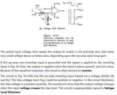
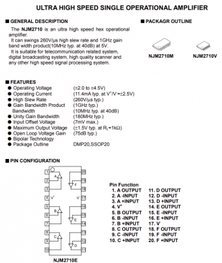
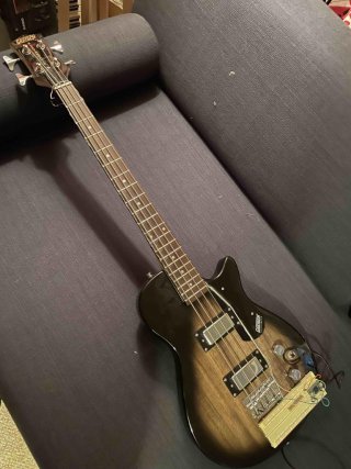
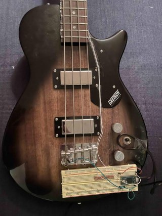
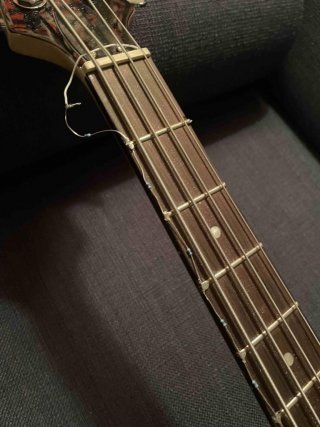
I've set out to build a MIDI bass guitar following a proven industry design. This "wired frets" design runs a circuit through each string which is completed by whichever fret is active. The active fret determines which MIDI note to trigger. I assumed a basic voltage divider was the right choice, so I bought an inexpensive bass and soldered 1K resistors between each fret. I'm hoping to build a one string prototype to prove out the idea before moving on to building a custom neck with built-in resistors. So far I've managed to track which fret is active/fretted by running the entire series of 20 resistors to one analog read pin. It's noisy so I added the filter seen below. This helped with tracking stability but also introduced unwanted slewing when moving more than one semitone up or down the neck. The next step is adding piezo saddles which will provide the amplitude signal for each string (again, just starting with one string.) While this will enable triggering the note-on event at the intended time (currently it's sent when a fret/note change is detected,) I also expect it will help with cleaner capture of note changes. Perhaps by allowing the filter to be reset on each pluck. The saddles are in the mail, so we'll see.
At this stage I'd appreciate advice on the general strategy. Is the voltage divider the right approach? If so, is there anything I should consider within the circuit to reduce noice/improve stability? I'm assuming a lower number of resistor steps in a given circuit will provide more stable tracking by providing larger value ranges per note. Should I break each string into two circuits? If that's necessary I assume I'll run out of analog read pins between the voltage dividers and the piezos (4 string bass, so 8 total in the case of one circuit/string, 12 if 2 circuits/string,) but I'm not sure if one Teensy would be able to keep up with measuring 4 (or 8) voltage dividers and 4 piezo amplitudes at a usable rate. If it can, should I consider an external ADC? If I am asking too much of one Teensy, should I consider using 2 or 4 Teensies for string processing and then one more for multiplexing into a single MIDI channel output?
Thanks in advance for any advice!
Code:
#include "MegunoLink.h"
#include "Filter.h"

int analogPin = 0;
int rawValueRange = 1024;
int numFrets = 20;
int values[20][2];
int lowestMidiNote = 41;
int midiChannel = 1;

long FilterWeight = 3;
ExponentialFilter<long> ADCFilter(FilterWeight, 0);

void setup() {
  // put your setup code here, to run once:
  for (int i = 0; i < numFrets; i++) {
    float coef = (float)i / (float)numFrets;
    values[i][0] = floor(rawValueRange * coef);
    values[i][1] = lowestMidiNote + i;
  }
}

int findNoteForValue(int value) {
  int minDiff = abs(value - values[0][0]);
  int * closest = { values[0] };

  for (int i = 1; i < numFrets; i++) {
    int diff = abs(value - values[i][0]);

    if (diff < minDiff) {
      minDiff = diff;
      closest = values[i];
    }
  }
//  Serial.println(closest[0]);
  return closest[1];
}

int oldNote = lowestMidiNote;

void loop() {
  // put your main code here, to run repeatedly:
  delay(1);

  int rawValue = analogRead(analogPin);
  ADCFilter.Filter(rawValue);
  int filteredValue = ADCFilter.Current();
  int note = findNoteForValue(filteredValue);
  String message = String(rawValue) + "," + String(filteredValue) + "," + String(note);
  Serial.println(message);

  if (note == oldNote) {
    // do nothing
  } else {
    usbMIDI.sendNoteOff(oldNote, 0, midiChannel);
    usbMIDI.sendNoteOn(note, 99, midiChannel);
    oldNote = note;
  }

  // MIDI Controllers should discard incoming MIDI messages.
  while (usbMIDI.read()) {
  }
}


