Dac8568--->dac8168

Anoat

Active member
Hello everyone,

It had been a while since I had been back:cool:.

I am currently programming a PCB with a DAC8168 (8 outputs 14bits).

I found a suitable piece of code to program it.
Code:
#include <Arduino.h>
#include <SPI.h>

#define syncPin PB8

unsigned int one;
unsigned int two;
unsigned int three;
unsigned int four;


void DAC8568Write(unsigned int prefix, unsigned int control, unsigned int address, unsigned int data, unsigned int feature) {

  one = (prefix << 4)|control;
  two = (address << 4)|(data >>12);
  three = data >> 4;
  four = (data << 4)|feature;
  digitalWrite(syncPin,LOW);
  SPI.transfer(one);
  SPI.transfer(two);
  SPI.transfer(three);
  SPI.transfer(four);
  digitalWrite(syncPin,HIGH); 
}

void DAC8568Reset()
{
  DAC8568Write(0b0001, 0b1100, 0x00, 0x00, 0x00) ;
}

void DAC8568InternalRef()
{
  DAC8568Write(0x00, 0x08, 0x00, 0x0000, 0x01) ;
}

void DAC8568SetVoltage(unsigned int channel,unsigned int voltage)
{
  DAC8568Write(0, 3, channel, voltage, 0) ;
}


void setup() 
{
  pinMode (syncPin, OUTPUT);
  digitalWrite(syncPin, HIGH);
  SPI.beginTransaction(SPISettings(48000000, MSBFIRST, SPI_MODE1));
  delay(200);
  DAC8568Reset();
  delay(200);
  DAC8568InternalRef();
  delay(200);
}


void loop() 
{
  unsigned int i;
  for (i=0;i<8;++i)
  {
    DAC8568SetVoltage(i,2700);
  }
  delayMicroseconds(100);
}

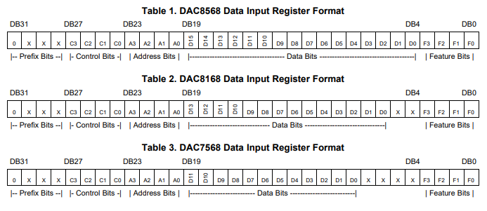
But here is nothing is simple in life, the piece of code that I found is made for a DAC8568 (8 outputs 16 bits), either I just have a modification to make, however I have trouble understanding how it organizes the bits to create a 32bit message:(. Perhaps you could enlighten me on the subject?

Code:
void DAC8568Write(unsigned int prefix, unsigned int control, unsigned int address, unsigned int data, unsigned int feature) {

  one = (prefix << 4)|control;
  two = (address << 4)|(data >>12);
  three = data >> 4;
  four = (data << 4)|feature;
  digitalWrite(syncPin,LOW);
  SPI.transfer(one);
  SPI.transfer(two);
  SPI.transfer(three);
  SPI.transfer(four);
  digitalWrite(syncPin,HIGH); 
}

So wouldn't it be easier to use a 32bit variable and send it in SPI:confused:?
Code:
unsigned long message;

void DAC8568Write(unsigned int prefix, unsigned int control, unsigned int address, unsigned int data, unsigned int feature) {
 
  message = (prefix << 28) | (control << 24) | (adress << 20) | (data << 4) | (feature);
  
  digitalWrite(syncPin,LOW);
  SPI.transfer(message);
  digitalWrite(syncPin,HIGH); 
}


Cordialement ANOAT
 
The code example you found for the DAC8568 will work perfectly fine for the DAC8168 as well.
These DAC's are very similar - the datasheet states: "The DAC7568, DAC8168, and DAC8568 are drop-in and function-compatible with each other".
The only difference is the number of data bits, 16 vs 14 vs 12. Even if you write 16 bit data into the 14 bit DAC8168, the lower 2 bits will be discarded:

TI.PNG

Page 35-37 of the datasheet show you the rest of the registers/commands that can be written - no difference except the number of data bits.

So wouldn't it be easier to use a 32bit variable and send it in SPI?
Yes, but you would need to use the SPI.transfer32() function [only available for Teensy 4.x]

Paul
 
Thank you for your answer,

I begin to understand, in fact SPI.tranfer sends only one byte.

I use a Teensy4x. I corrected the code to directly transmit a 32-bit message.
Code:
#include <Arduino.h>
#include <SPI.h>

byte syncPin = 14 ;

unsigned int one;
unsigned int two;
unsigned int three;
unsigned int four;

unsigned long message;

void DAC8568Write(unsigned int prefix, unsigned int control, unsigned int address, unsigned int data, unsigned int feature) {
 
  message = (prefix << 28) | (control << 24) | (address << 20) | (data << 4) | (feature);
  
  digitalWrite(syncPin,LOW);
  SPI.transfer32(message);
  digitalWrite(syncPin,HIGH); 
}

void DAC8568Reset()
{
  DAC8568Write(0b0001, 0b1100, 0x00, 0x00, 0x00) ;
}

void DAC8568InternalRef()
{
  DAC8568Write(0x00, 0x08, 0x00, 0x0000, 0x01) ;
}

void DAC8568SetVoltage(unsigned int channel,unsigned int voltage)
{
  DAC8568Write(0, 3, channel, voltage, 0) ;
}


void setup() 
{
  pinMode (syncPin, OUTPUT);
  digitalWrite(syncPin, HIGH);
  SPI.beginTransaction(SPISettings(48000000, MSBFIRST, SPI_MODE1));
  delay(200);
  DAC8568Reset();
  delay(200);
  DAC8568InternalRef();
  delay(200);
}


void loop() 
{
  unsigned int i;
  for (i=0;i<8;++i)
  {
    DAC8568SetVoltage(i,2700);
  }
  delayMicroseconds(100);
}

Is there a particular interest to transfer the message in 32bits rather than in 8bits?


Merci ANOAT
 
Thank you for your answer,

I begin to understand, in fact SPI.tranfer sends only one byte.

I use a Teensy4x. I corrected the code to directly transmit a 32-bit message.
Code:
#include <Arduino.h>
#include <SPI.h>

byte syncPin = 14 ;

unsigned int one;
unsigned int two;
unsigned int three;
unsigned int four;

unsigned long message;

void DAC8568Write(unsigned int prefix, unsigned int control, unsigned int address, unsigned int data, unsigned int feature) {
 
  message = (prefix << 28) | (control << 24) | (address << 20) | (data << 4) | (feature);
 
  digitalWrite(syncPin,LOW);
  SPI.transfer32(message);
  digitalWrite(syncPin,HIGH);
}

void DAC8568Reset()
{
  DAC8568Write(0b0001, 0b1100, 0x00, 0x00, 0x00) ;
}

void DAC8568InternalRef()
{
  DAC8568Write(0x00, 0x08, 0x00, 0x0000, 0x01) ;
}

void DAC8568SetVoltage(unsigned int channel,unsigned int voltage)
{
  DAC8568Write(0, 3, channel, voltage, 0) ;
}


void setup()
{
  pinMode (syncPin, OUTPUT);
  digitalWrite(syncPin, HIGH);
  SPI.beginTransaction(SPISettings(48000000, MSBFIRST, SPI_MODE1));
  delay(200);
  DAC8568Reset();
  delay(200);
  DAC8568InternalRef();
  delay(200);
}


void loop()
{
  unsigned int i;
  for (i=0;i<8;++i)
  {
    DAC8568SetVoltage(i,2700);
  }
  delayMicroseconds(100);
}

Is there a particular interest to transfer the message in 32bits rather than in 8bits?


Merci ANOAT

Hello, I have noticed that with the code you posted, for the RESET command you are sending
0x1c000000 = 00011100000000000000000000000000

However you would want to send
0x07000000 = 00000111000000000000000000000000

As you can see in page 39, Table 6, of the datasheet "DAC7568, DAC8168, DAC8568", it seems you are forgetting about DB29, and DB28, because on the 2nd place it says "DB30-DB28"
 
Back
Top