Mixed voltage sources

JoeMama

Member
Hello everyone,

I'm a software developer by trait, so I am a bit unsure about my current plans.
I need to generate some control voltages and figured a 12 bit resolution PWM signal after some filtering should be a good basis.
Now, the actual CV should be +/-4V, so some op-amp correction is necessary. I have simulated how a Teensy 4.0 12-bit PWM signal would perform over here:

http://falstad.com/circuit/circuitj...ueoAGIQKPgGyMEAAEQArgAXACeAB0AM4AYVnTgANrRmEA

Now, this is all fine. However, the op-amp needs to be powered, too.
For this, I wanted to use two 12V power supply packages, something like the IRM-01-12 by Mean Well.
I have used two of them to get dual rail power before, so this should work here as well.

However, because the Teensy will also be a MIDI receiver through its USB port, I need to either power the Teensy externally, or make sure that the two grounds won't mess with the signals.
The latter is where I am unsure: Should I connect the ground of my dual rail power supply with the Teensy's ground, or leave it as is?

I fear that, since these two grounds are sort of independent of one another, the signal reference could shift significantly.
Since the project is still in its infancy, I am very much open for any suggestion.
Preferably, I would like to power the Teensy with a 3.3V regulated source, such that all grounds are the same. But again, I am not sure if this is a problem to begin with.

/edit:
Oh yea, the 1.65V in the simulation above is just hard-'coded', it would originate from the dual rail power supply and a voltage divider + op amp.
 
I would choose rail-to-rail opamp and use +/-5V supply personally. There are chips expressly designed for generating -5V from +5V using switched-capacitor method that mean you can just use +5V supply for everything.
 
While you haven't directly addressed my main question, which is "is it okay to connect these two separate grounds", I think your method, if powered by the microcontroller, would make the question irrelevant.
I have a bunch of TL074 quad op-amps around, so I would use one of them since it works with 5V just as well.
Before, I had to have dual rail supplies that can provide +500mA each, but since this is low power anyways ..
what kind of chips are you referencing? Can you please give me an example?
 
> I have a bunch of TL074 quad op-amps around, so I would use one of them since it works with 5V just as well.

No, it doesn't. TL072 and TL074 do not work well a couple of volts away from the rails, which is fine with a ±10V swing on ±12V or ±15V rails; not so great with ±5V rails. In particular, swinging closer than 2V from the negative rail will lead to the output becoming positive (polarity inversion). So if you go for lower voltage rails, use rail-to-rail input and output op-amps.

Filtered PWM is slow to respond, so consider using one of the many inexpensive DACs to generate your CV.

Yes, you will need to tie the Teensy ground to the PWM or DAC ground. However, you might get issues with noise or hum on the USB input, if so consider an opto isolator.
 
Interesting, I wasn't aware of these pitfalls with op-amp ICs like the TL07X series.
To be fair, I wasn't even aware that non-rail-to-rail op-amps exist, so thanks for bringing that up.

I am aware that filtered PWM signals are inherently lagging behind change, but I have tested that even a 2 ms delay (or bend to the next value) is as good as imperceptible to (my) ears when used as a 1V/oct CV source, even at octave(s)-apart-values.
Again, at least for my application. I have fine-tuned the capacitor values to reflect real component values between the posts, and I'm happy with the results so far.
Alright, my usual electronics supplier seems to have a lack of variety, but the MCP 6004 seems to be suitable.

Assuming the above is fine, I still need to power the IC(s).
There are chips expressly designed for generating -5V from +5V using switched-capacitor method that mean you can just use +5V supply for everything.
What are these types of ICs called? I'd like to check out what my usual supplier has in stock. If you guys have any specific ICs you can recommend for this I'd like to hear.
 
The term you gave is not quite answering my question. I was asking for the name of the category these ICs belong to, not the general concept of generating negative voltages.
All I could find was DIY charge pump circuits or linear voltage regulators, but not anything close to what MarkT was mentioning.
 
What are these types of ICs called?

LMC7660 or TL7660 are probably the most popular way to get -5V for a few opamps when you have only +5V.

https://www.ti.com/product/LMC7660

https://www.ti.com/product/TL7660

The original LM7660 chip by National Semiconductor (TI acquired National in 2011) has been around since at least the early 1980s. The "LM" version was (probably) NMOS or some other older silicon process. It was replaced by "LMC" in the 1990s as CMOS became the norm. Many compatible "7660" chips are made by other companies, because LM*7660 has about 40 years as the go-to part for getting -5V to run a few opamps.

It's very easy to use. You just add a few capacitors, usually 10uF. Most of the example schematics show 2 caps, but don't forget to add a similar size capacitor between 5V and GND, since it works this voltage conversion magic by drawing pulses of current.

Keep in mind the -5V isn't regulated. So if you use opamps that draw many mA current, expect it to sag to something like -4.5V.
 
Thank you Paul, I suppose this is the type of IC MarkT had in mind.
I guess these ICs fall under the blanket term (switched capacitor) "voltage converters", judging by how TI calls them on their product pages.
The LMC7660 datasheet is looking promising, the example schematic plus your description couldn't be more clear.
Thanks for the help, for the few op-amp ICs I'll be using this will be more than enough, since the circuit utilizing these CVs is always mixing these with at least 100K ohms of resistance with another op-amp right after.

And briefly, @BriComp: I am not sure if its my browser cache messing up or you've deleted your response, but my few cents: Yes, you are correct that some ICs show up.
But the point remains that I was asking about the type of IC MarkT was referring to, or better yet, specific ICs known to work well for applications with low-voltage devices like the Teensy.
Still, I appreciate your input, see your point and will keep what you said in mind next time I need to research new (to me) types of ICs.
Cheers to everyone for the help!
 
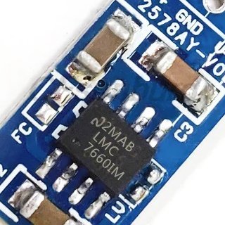
For a quick example of how widespread "7660" compatible parts are, here's a little breakout board found on Aliexpress.

lm7660.jpg

If you look closely at the photo, you can see the chip originally had some other marking which has been printed over with LMC7660. It even has a little curved "N" meant to look similar to the National Semiconductor logo. Someone, somewhere in China is probably still misrepresenting 7660 parts this way, even though TI acquired National over a decade ago!

natsemi.png

Normally I'd say to beware of counterfeit parts. But LMC7660 has been a staple of analog engineers for so long, with several companies making compatible parts, and it's based on such mature technology, that you're probably fine with pretty much any "7660" part that claims to be compatible, even this sort of blatant counterfeit.
 
Interesting, those off-brand IC shenanigans are kind of expected of aliexpress.
What's more is that it looks more like a bad photoshop job, the perspective seems slightly off. Good chuckle.
 
The MAX1681 is the chip I've used. Can be used also as a voltage doubler, 125mA max output, 90% efficiency, currently available. Much lower output resistance than the 7660.
 
Back
Top