Debouncing circuit on a T4

Frukost

Well-known member
I am testing Ganssles debounce circuit (as described here) for a T4. The circuit looks like this:
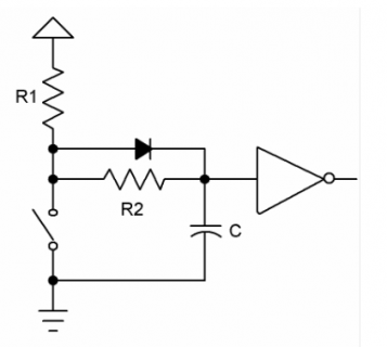
Debouncekrets.PNG

Vcc is sourced from T4 3,3V pin.
R1, R2 = 100K (I chose high R values to make debouncing times more obvious as a first test)
C = 1uF
Diode = 1N4148
The only deviation from the schematic is that I've omitted the schmitt trigger, based on the assumption that the T4 has onboard schmitt triggers.

Code:
#include <Arduino.h>

constexpr uint8_t ledPin = 13;
constexpr uint8_t switchPin = 11;

void setup() {
    Serial.begin(115200);

    pinMode(switchPin, INPUT);
    pinMode(ledPin, OUTPUT);
}

void loop() {
    static bool previousSwitchState{};
    bool switchState = digitalRead(switchPin);

    if (switchState != previousSwitchState) {
        Serial.print(String(switchState));
        digitalWrite(ledPin, !switchState);  // Active low

        previousSwitchState = switchState;
    }
}

My problem is that when I look at the Serial.print():ed switch states, the circuit doesn't appear to reduce bouncing at all. I have looked over the physical circuit several times, and I can't detect any errors in the wirings.

However, looking at the Serial.print() output the logic levels are inverted, which they - to my understanding - shouldn't be with an inverting schmitt trigger operating in the circuit. Am I right in assuming that if a schmitt trigger had been operating as expected, the button states shouldn't be inverted?

Looking at 12.3.1.1 in the i.MX RT1060 Processor Reference Manual it says that one of the input driver characteristics are selectable schmitt trigger or CMOS input mode. Does this mean that the errors are caused because of a disabled schmitt trigger, and if so, how do I enable it?

Are there any other errors/theories that can explain my problem?
 
The built-in schmitt trigger for each pin is configurable via bit 16 (HYS_1_Hysteresis_Enabled in the pdf) in the pad control registers (accessible with the portControlRegister macro in pins_arduino.h). It's non-inverting though, while the one in your schematic is inverted.
 
Last edited:
Where are 3.3V and Pin #11 on the diagram?

Rather than directly using 3.3V, does it change using INPUT_PULLUP on switchPin #11 instead of INPUT?
 
Thanks for your replies!

The built-in schmitt trigger for each pin is configurable via bit 16 (HYS_1_Hysteresis_Enabled in the pdf) in the pad control registers (accessible with the portControlRegister macro in pins_arduino.h). It's non-inverting though, while the one in your schematic is.
Since I have no experience in working with memory registers, do you know what the default configuration is? Also, how do I change the configuration, if necessary?

The inverting aspect isn't crucial, as the final logic level can be easily handled in code.

Where are 3.3V and Pin #11 on the diagram?
Good question! 3.3V is coming from the upward arrow symbol (i don't know the proper name), at R1. Pin 11 is wired to the positive capacitor pin, where the schmitt trigger is wired in the schematic.

Rather than directly using 3.3V, does it change using INPUT_PULLUP on switchPin #11 instead of INPUT?
Using INPUT_PULLUP makes everything nonresponsive. Nothing in the Serial monitor, nothing from the onboard LED.

As an alternative, I tried pin 6 with the same results.
 
Last edited:
The only deviation from the schematic is that I've omitted the schmitt trigger

The other change made is the value of R2. 100K ohms is a very large value for a pull down resistor and will make the circuit susceptible to noise pickup.

Using INPUT_PULLUP makes everything nonresponsive.

Again the pulldown resistor value is too large.
 
The other change made is the value of R2. 100K ohms is a very large value for a pull down resistor and will make the circuit susceptible to noise pickup.
Thanks for pointing that out. However, I should probably mention that I started off with R values in the 15-20K range before experimenting with greater values, and the problem has persisted for all resistor values...
 
Since I have no experience in working with memory registers, do you know what the default configuration is? Also, how do I change the configuration, if necessary?

The default is hysteresis disabled since it adds a small delay. To turn it on for pin 11:

Code:
*(portControlRegister(11)) |= IOMUXC_PAD_HYS;

It's possible you might not even need a debounce circuit with it enabled.
 
With pinMode using INPUT_PULLUP noted in post #3 it should default to IOMUXC_PAD_HYS:

Code:
	} else if (mode == INPUT_PULLUP) {
			*(p->pad) = IOMUXC_PAD_DSE(7) | IOMUXC_PAD_PKE | IOMUXC_PAD_PUE | IOMUXC_PAD_PUS(3) | IOMUXC_PAD_HYS;
 
If using the internal pull up then you in effect have a voltage divider between R2 and the pullup, R2 needs to be significantly smaller than the internal pullup in order to avoid an undefined input state.
Internal pullups are typically in the 10-40k region.
Drop the resistors to 1k and see what happens.

Indeed - not an EE here - and didn't look at the circuit or values ... except to see I couldn't tell where 3.3V and the input were even located.

But observed minimal normal usage is with INPUT_PULLUP alone to supply the voltage and a resistor to ground in some fashion to safely drop the voltage, and that proper capacitor selection/placement will give a circuit measurable debounce.
 
Thanks for your feedback! Unfortunately, using 1K resistors increased bouncing.

The default is hysteresis disabled since it adds a small delay. To turn it on for pin 11:

Code:
*(portControlRegister(11)) |= IOMUXC_PAD_HYS;

Thanks for clarifying! However, this didn't have any effect on the bounces.
 
Use an external 74LVC14 for real hysteresis?

Why aren't you debouncing in software BTW? Its cheaper, you only need a pull-up (and that could be internal even) - the only reason not to do debouncing in software is if that input is attached to an interrupt routine.
 
Use an external 74LVC14 for real hysteresis?
I started with the assumption that the gpio drivers on T4 would suffice for schmitt trigger duties. I still don't understand whether I'm doing something wrong, or I'm expecting the impossible from the T4. But yeah, an external chip could be my next option.

Why aren't you debouncing in software BTW? Its cheaper, you only need a pull-up (and that could be internal even) - the only reason not to do debouncing in software is if that input is attached to an interrupt routine.
This is a test which eventually is supposed to end up as a debounce circuit for the gpio's of an mcp23s17 gpio expander. It can't be programmed for software debouncing, and will also communicate with interrupts to the T4.
 
I think I know what's going on now, and wanted to check with you if this is could be a feasible explanation:

If we assume that the debounce circuit in fact works the way it's supposed to, then this could be a sampling problem. Reading the input at full processing speed of the T4 and serial port, the T4 will capture forbidden area states of the input. Of course, a schmitt trigger will aid in shortening rising/falling times, but a high enough sampling frequency will still capture the remaining slope time of the forbidden area, resulting in deceptive button bouncing.

All of this could have been clarified with the aid of an oscilloscope, but since I don't have one, reading button presses in code was my only option.

I tried lowering the sampling frequency by reading the input every millisecond, resulting in zero bouncing:

Code:
#include <Arduino.h>

constexpr uint8_t ledPin = 13;
constexpr uint8_t switchPin = 11;
constexpr uint8_t readInterval = 1;

void setup() {
    Serial.begin(115200);

    pinMode(switchPin, INPUT);
    pinMode(ledPin, OUTPUT);
}

void loop() {
    bool switchState = digitalRead(switchPin);
    static uint32_t previousTime{};

    if (previousTime <= millis() - readInterval) {
        Serial.print(String(switchState));
        previousTime = millis();
    }
}
 
Back
Top