SPI Bus only first declared chip select board reads properly.

ctlang

Member
Using three MAX31865 boards to measure three different RTDs. Have them all hooked up on the same SPI bus. If I call them individually all three work flawlessly. When I try to put them all together on the first one I initialize works!


In code below. If I comment out them individually they each work. But as shown, only the RTD board on Chip Select pin 8 works :(

Code:
#include <Adafruit_MAX31865.h>

// Use software SPI: CS, DI, DO, CLK
//Adafruit_MAX31865 thermo = Adafruit_MAX31865(8, 11, 12, 13);
// use hardware SPI, just pass in the CS pin
Adafruit_MAX31865 thermo = Adafruit_MAX31865(8);
Adafruit_MAX31865 thermo2 = Adafruit_MAX31865(9);
Adafruit_MAX31865 thermo3 = Adafruit_MAX31865(10);

// The value of the Rref resistor. Use 430.0 for PT100 and 4300.0 for PT1000
#define RREF      4300.0
// The 'nominal' 0-degrees-C resistance of the sensor
// 100.0 for PT100, 1000.0 for PT1000
#define RNOMINAL  1000.0

void setup() {
  Serial.begin(115200);
  Serial.println("Adafruit MAX31865 PT100 Sensor Test!");

//  thermo.begin(MAX31865_4WIRE);  // set to 2WIRE or 4WIRE as necessary
  thermo2.begin(MAX31865_4WIRE);  // set to 2WIRE or 4WIRE as necessary
  thermo3.begin(MAX31865_4WIRE);  // set to 2WIRE or 4WIRE as necessary
  thermo.begin(MAX31865_4WIRE);  // set to 2WIRE or 4WIRE as necessary


}


void loop() {
  uint16_t rtd_debug1 = thermo.readRTD();
  float ratio1 = rtd_debug1;
  ratio1 /= 32768;

  uint16_t rtd_debug2 = thermo2.readRTD();
  float ratio2 = rtd_debug2;
  ratio2 /= 32768;

  uint16_t rtd_debug3 = thermo3.readRTD();
  float ratio3 = rtd_debug3;
  ratio3 /= 32768;

  Serial.println("Res1      Res2        Res3");
  Serial.print(RREF*ratio1,2);  Serial.print("    "); Serial.print(RREF*ratio2,2);  Serial.print("    "); Serial.println(RREF*ratio3,2);
  Serial.println("Temp1      Temp2        Temp3");
  Serial.print(thermo.temperature(RNOMINAL, RREF));  Serial.print("       "); Serial.print(thermo2.temperature(RNOMINAL, RREF));  Serial.print("       "); Serial.println(thermo3.temperature(RNOMINAL, RREF));


  // Check and print any faults
  uint8_t fault = thermo.readFault();
  if (fault) {
    Serial.print("Fault 0x"); Serial.println(fault, HEX);
    if (fault & MAX31865_FAULT_HIGHTHRESH) {
      Serial.println("RTD High Threshold"); 
    }
    if (fault & MAX31865_FAULT_LOWTHRESH) {
      Serial.println("RTD Low Threshold"); 
    }
    if (fault & MAX31865_FAULT_REFINLOW) {
      Serial.println("REFIN- > 0.85 x Bias"); 
    }
    if (fault & MAX31865_FAULT_REFINHIGH) {
      Serial.println("REFIN- < 0.85 x Bias - FORCE- open"); 
    }
    if (fault & MAX31865_FAULT_RTDINLOW) {
      Serial.println("RTDIN- < 0.85 x Bias - FORCE- open"); 
    }
    if (fault & MAX31865_FAULT_OVUV) {
      Serial.println("Under/Over voltage"); 
    }
    thermo.clearFault();
  }
  Serial.println();
  delay(1000);
}
 
You might want to look at this article Paul wrote some time ago:

I found with doing Uncanny Eyes with two displays on the same SPI bus, I needed to add pull-up resistors for some displays. With other displays, pull-up registers did not work, but I suspect pull-down might have worked.

The other issue might be having the proper tri-state capability.
 
Sometimes helps to de-select all of the SPI devices before initializing them. Try adding this to the beginning of setup:

Code:
pinMode(8, OUTPUT);
pinMode(9, OUTPUT);
pinMode(10, OUTPUT);
digitalWriteFast(8, HIGH);
digitalWriteFast(9, HIGH);
digitalWriteFast(10, HIGH);

Otherwise, agree that maybe the SPI devices are not tri-stating correctly.
 
thanks for the tips. No luck so far.
Added 4.7kOhm pullup resistor to each chip select.
Added a voltage divider to the MISO line.
Added
Code:
SPI.endTransaction();
calls to the end of each call to the chips.

Nothing has worked so far.
 
The voltage divider on MISO is a test, not a solution. What voltage did you measure?

When all SPI chips are disabled, the MISO signal should “float” to approximately half the Vcc voltage. If any device is still driving the MISO line, you’ll see a logic high (usually close to 3.3V or 5.0V) or logic low (close to zero volts). This test is so easy, it should always be performed by designers of Arduino compatible products.

If your SPI slave devices do not tristate correctly, you will need to add a tristate buffer such as SN74AHCT125. You can then drive the output enable pins to allow data to flow to the selected slave SPI device.
 
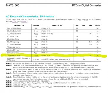
The MAX31865 seems to say the SDO pin does go high impedance when CS is high.

screenshot.jpg

Still might be worthwhile to do the voltage divider test just to make sure MISO it really isn't being driven by anything while all the CS signals are high. But unless some other SPI device is connected, seems unlikely this is actual problem.
 
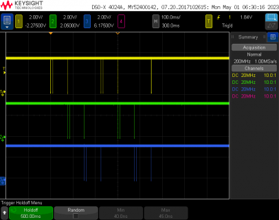
I ran the code from msg #1 on a Teensy 4.1 with no hardware connected, just to quickly look at the 3 chip select signals. Indeed it seems to be generating them on the 3 pins.

file1.png

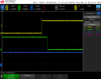
When I zoom in, looks like only 300ns from pin 8 high to pin 9 low.

file2.png

Maybe this is fine, but as a quick and easy test, try adding delays before you read each sensor. I see inside the library Adafruit used delays of 10 and 65 ms, and they configure a slow 1 MHz clock. Perhaps these are pretty slow devices? Maybe such a short time is an issue? Just adding 10ms delays in the main program after attempting to read each sensor might be worth a quick try.
 
thanks for the help y'all. When I did the voltage divider it was sitting high, not floating...

Looking back through the Adafruit_MAX31865 library which uses the Adafruit_SPIDevice library, I thought Paul found the problem. But additionally delays in the main code between thermo.readRTD() calls doesn't solve it.

Code:
/**************************************************************************/
/*!
    @brief Read the raw 16-bit value from the RTD_REG in one shot mode
    @return The raw unsigned 16-bit value, NOT temperature!
*/
/**************************************************************************/
uint16_t Adafruit_MAX31865::readRTD(void) {
  clearFault();
  enableBias(true);
  delay(10);
  uint8_t t = readRegister8(MAX31865_CONFIG_REG);
  t |= MAX31865_CONFIG_1SHOT;
  writeRegister8(MAX31865_CONFIG_REG, t);
  delay(65);

  uint16_t rtd = readRegister16(MAX31865_RTDMSB_REG);

  enableBias(false); // Disable bias current again to reduce selfheating.

  // remove fault
  rtd >>= 1;

  return rtd;
}


it seems the readRegister16 line (shown above) should also have delay after it as it calls this function from Adafruit_SPIDevice (shown below). Regardless adding delays in the main loop should resolve this...


Code:
bool Adafruit_SPIDevice::write_then_read(const uint8_t *write_buffer,
                                         size_t write_len, uint8_t *read_buffer,
                                         size_t read_len, uint8_t sendvalue) {
  beginTransactionWithAssertingCS();
  // do the writing
#if defined(ARDUINO_ARCH_ESP32)
  if (_spi) {
    if (write_len > 0) {
      _spi->transferBytes(write_buffer, nullptr, write_len);
    }
  } else
#endif
  {
    for (size_t i = 0; i < write_len; i++) {
      transfer(write_buffer[i]);
    }
  }

#ifdef DEBUG_SERIAL
  DEBUG_SERIAL.print(F("\tSPIDevice Wrote: "));
  for (uint16_t i = 0; i < write_len; i++) {
    DEBUG_SERIAL.print(F("0x"));
    DEBUG_SERIAL.print(write_buffer[i], HEX);
    DEBUG_SERIAL.print(F(", "));
    if (write_len % 32 == 31) {
      DEBUG_SERIAL.println();
    }
  }
  DEBUG_SERIAL.println();
#endif

  // do the reading
  for (size_t i = 0; i < read_len; i++) {
    read_buffer[i] = transfer(sendvalue);
  }

#ifdef DEBUG_SERIAL
  DEBUG_SERIAL.print(F("\tSPIDevice Read: "));
  for (uint16_t i = 0; i < read_len; i++) {
    DEBUG_SERIAL.print(F("0x"));
    DEBUG_SERIAL.print(read_buffer[i], HEX);
    DEBUG_SERIAL.print(F(", "));
    if (read_len % 32 == 31) {
      DEBUG_SERIAL.println();
    }
  }
  DEBUG_SERIAL.println();
#endif

  endTransactionWithDeassertingCS();

  return true;
}
 
Back
Top