Teensy Micromod not blinking

bobpellegrino

Active member
I have several Teensy Micromods that seem to be working, except for the Blink program.

The LEDs work in other contexts, like when downloading a program or going through the 15 sec reset procedure (which completes fine). But when I load in Blink the Prog LED flashes and then...nothing.

I changed the Blink program to:


void setup() {
// initialize digital pin LED_BUILTIN as an output.
pinMode(LED_BUILTIN, OUTPUT);
}

// the loop function runs over and over again forever
void loop() {
digitalWrite(LED_BUILTIN, HIGH); // turn the LED on (HIGH is the voltage level)
Serial.print('.');
Serial.print(LED_BUILTIN);
delay(1000); // wait for a second
digitalWrite(LED_BUILTIN, LOW); // turn the LED off by making the voltage LOW
delay(1000); // wait for a second
}


The Serial Monitor shows .13.13.13.13.13

so the Teensy is working, but no blink.

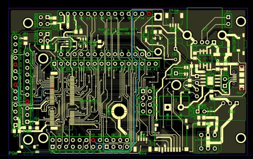
The Micromod is not plugged into an ATP board, it is plugged into a custom manufactured board. But the fact that the Teensy boots up and runs leads me to think that the custom carrier board is ok. But the fact that the LED flashes in other contexts leads me to think that the Micromod board is ok. But *something* is not ok.

Ideas?

One other piece of info is that when you first plug in these boards, before downloading anything, they print out "Teensy Micromod Pin Test" to the serial monitor.
 
I'm not sure about those "other contexts", but first guess would be the LED is not on the correct pin or some other hardware issue. Can you show the schematic?
 
A normal Teensy4 has two LEDs: a red one that's controlled by the separate programming chip and an orange one, connected to the LED_BUILTIN pin. From looking at the schematic the micromod only has the first one. You can't control it from code.

Edit: My bad, it is shown in a separate section of the schematic as "Stat LED". Apparently it's blue, the programming LED is yellow.
 
Last edited:
A normal Teensy4 has two LEDs: a red one that's controlled by the separate programming chip and an orange one, connected to the LED_BUILTIN pin. From looking at the schematic the micromod only has the first one. You can't control it from code.

Edit: My bad, it is shown in a separate section of the schematic as "Stat LED". Apparently it's blue, the programming LED is yellow.

Ok, so part of my confusion is the color of the LEDs. Since the Prog one is yellow on the Micromod, I thought that it was the LED_BUILT_IN. So, on the Micromod there is a yellow LED that corresponds to the Red LED on the regular Teensy. And there is a blue LED which is pin 13 LED_BUILTIN.

I can say that I have never seen anything blink Blue on the Micromod, so there's my problem. But what are the chances that all 6 Micromod boards have a bad Blue LED?I don't think my carrier board could cause that, right?

BTW, I think it was an unfortunate choice to change the color of the LEDs. I wonder what was gained.
 
I don't think my carrier board could cause that, right?

Don't think so, unless it connects pin 13 directly to ground... but then the board would probably shut off/reboot as soon as it tried to drive it high.

It's probably very unlikely (I think the micromod uses more or less the same boot sequence as a regular Teensy?) but maybe the padmux for pin 13 isn't set to the GPIO port?
 
Last edited:
...
The LEDs work in other contexts, like when downloading a program or going through the 15 sec reset procedure (which completes fine). But when I load in Blink the Prog LED flashes and then...nothing.
...

The 15 sec Restore reloads a factory Blink, and the Pin#13/LED_BUILTIN works then it is indicated?

If a normal Blink can't do the same thing maybe the TeensyDuino IDE (#1 or #2 ???) is somehow corrupted?

Pressing the Button will 'light' the PROG LED and that works and was used for timing the 15 Sec Restore and shows activity during upload? And then the 'other' STAT LED was blinking after the 15 Sec Restore?

No, I was mistaken when I used the plural of LED. The Blue LED never lights. The Prog LED lights during upload and the 15 sec restore completes as expected judging from the timing and sound of the windows beeps. But the Blue LED never lights.

When I apply voltage externally to the Blue LED it does light, so it is not burned out. When I set pin 13 High there is no signal on pin 57 of the M.2 connector. When I set other pins High, there is signal on the M.2 connector.

Seems like bad Mmod, but all of them? I tried 8 so far, 2 bought last year, 5 bought last month, and 1 lockable. I'm checking for shorts now.
 
...
The LEDs work in other contexts, like when downloading a program or going through the 15 sec reset procedure (which completes fine). But when I load in Blink the Prog LED flashes and then...nothing.
...

The 15 sec Restore reloads a factory Blink, and the Pin#13/LED_BUILTIN works then it is indicated?

If a normal Blink can't do the same thing maybe the TeensyDuino IDE (#1 or #2 ???) is somehow corrupted?

Pressing the Button will 'light' the PROG LED and that works and was used for timing the 15 Sec Restore and shows activity during upload? And then the 'other' STAT LED was blinking after the 15 Sec Restore?
 
defragster, I think we were talking over each other. The prog LED works normally in all respects. The stat (blue) led does not light under program control but does if I apply voltage to the pins. There is no High signal on pin 57 of the M.2 when the program sets pin 13 High. I just confirmed there are no shorts between Pin 57 of the M.2 and either GND or 3v3.
 
What @defragster was mentioning, is that the 15 second restore, should reprogram the IMXRT chip back to the original ship state, which includes blinking the USER (pine 13) LED.
Again if that is not working, it is maybe something to do with your setup.

So for example if you take your board without a teensy MM installed, and use something like an OHM meter. Is there a short from PIN 13 to GND? (or 3.3v) or to nearby pins?

Do you have a different adapter to try them with like one of the ones from Sparkfun? Does it blink in those?
 
Gotcha. The 15 sec restore *appears* to complete normally, but the blue LED does not blink. My own Blink program runs and prints out on Serial Monitor, but no blue blink. I confirmed no shorts on my carrier board.

It was a stupid move on my part not to have an ATP board on hand for testing, so now I have to wait until at least Wednesday to continue testing. A DMM between pin 57 of the Mmod socket and the anode of the LED shows 1000 ohms which corresponds to the 1k resistor shown in the T Mmod schematic.
 
defragster, I think we were talking over each other.
...

Indeed we did - I typed and left for lunch without hitting POST :)

But as @KurtE notes - after 15S Restore if the 'other' LED isn't blinking then something is wrong.

Once the flash at 13 secs with Button release, it will take ~2 minutes where the PROG/Orange LED is busy/On as the FLASH is erased and then the factory blink is put in place.
Then on the ATP the Blue/STAT LED does the one second Blink.

If the ~2 minutes passes without interruption and then the ORANGE LED goes out the Blue should be flashing ...


Just did that here with stopwatch with Teensy_MM on an ATP board plugged into Cell Phone Power only charge USB-C to see that.
 
Gotcha. The 15 sec restore *appears* to complete normally, but the blue LED does not blink. My own Blink program runs and prints out on Serial Monitor, but no blue blink. I confirmed no shorts on my carrier board.

It was a stupid move on my part not to have an ATP board on hand for testing, so now I have to wait until at least Wednesday to continue testing. A DMM between pin 57 of the Mmod socket and the anode of the LED shows 1000 ohms which corresponds to the 1k resistor shown in the T Mmod schematic.
What about the resistance from pin 57 to GND?

Note: i.e. are you using Pin 13 on your breakout board. For example, on my breakout board:
Screenshot.jpg
I have Pin 13 going to several locations. Both for basic breakout as well as the ability to do SPI to different TFT displays. The outer row for ILI9341 and ILI9488 and the inner row for Adafruit boards like ST7789 as you can see in this poor quality picture.
Screenshot1.jpg
The other display is connected up to an T4.1

So possibly something connected up on your board for SPI that is shorted? Or maybe an etch or one of the pads is shorted... That would be the first things I would check.

And if it were me, I would run sketch like the one that @defragster and I played with awhile back. I most recently (as in about 2 weeks ago) posted it again for a different issue.
In the thread: https://forum.pjrc.com/threads/5573...3-x-and-beyond?p=324323&viewfull=1#post324323

When you run it, you can switch between trying to pull all of the IO pins high (INPUT_PULLUP) or low (INPUT_PULLDOWN) and then
if you take a jumper wire and connect one end to the opposite value (GND for the INPUT_PULLUP) and then try temporarily connect the other end of wire to
each of pin of interest.

It will cycle through all of the pins looks for low values in this case and should detect the one you are touching and print out the logical pin number.

And it can indirectly imply some shorts, by for example if you touch D13 and both D13 and D12 both go low (or high in other configurations) then there may be a problem.

Also when we switch between the two modes it also tries to detect shorts by lets say set each pin HIGH and all of the others INPUT_PULLDOWN and see if others are HIGH ...
Anyway sometimes that has helped me detect things like this.

Good luck
 
KurtE, it's a good point-- I only checked for shorts, but not resistance. Partially because it's easier to listen for the beep rather than look at the DMM while targeting those ridiculously small SMT pins. When I was young I wielded regular probes. Then at middle age I had to stick those retractable hook clips on my probes to get at IC pins. Now I have to stick a sharp sewing needle into the hook clips which are stuck on the end of my probes. SMT was invented by young guys.

Thanks for the pointer to the sketch, I'll try it right now.
 
KurtE:

Thanks to your handy HiLow sketch I was able to determine that pin 13 was being held low by a buffer with a floating input. Thank you so much for your help.
 
KurtE:

Thanks to your handy HiLow sketch I was able to determine that pin 13 was being held low by a buffer with a floating input. Thank you so much for your help.

You are welcome... As I mentioned in prevous post, @defraster did a lot of the HiLow test...
 
KurtE and @defraster:

Your sketch was critical because there was no short on the carrier board with the power off, it was a power-on condition only. The only other way to find the problem would have been a logic analyzer which my board does not have the test pins for. And I could never get clips onto that M.2 connector.
 
Great it helped someone ... again ... good sharing @KurtE

It's come in handy more than a few times. And especially on the T_Micromod where it is always on a board with the obscured pin mapping not being on a given labeled pad.
 
Back
Top