Hi! I was wondering if anybody could help me make sense of the following.
I made a PCB that hosts a Teensy 4.1 and various IC's that communicate over I2C and SPI including six MAX31865 RTD-to-Digital Converters.
I'm trying to get the Teensy to communicate with one (any) of the MAX31865's over SPI but am running into some problems.
It works as expected but when I start to send out (high frequency) PWM signals on a, for the MAX31865, irrelevant pin, the communication stops working.
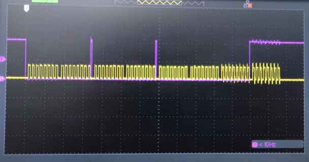
I connected a scope to the CS and SCK pins and made videos of both scenarios (with and without the PWM signal running in the background).
As you can see, one loop consists of two 2-byte transfers and one 3-byte transfer and in between the transfers the CS goes high as expected.
With the PWM signals running, the CS seems loose sync with the SCK over time. Looking at the code, this seems only possible if SPI.transfer() returns before the actual transfer has finished.
If I put a SPI.begin() command in front of each SPI.beginTransaction() this effect is somewhat negated but some data is still coming in corrupted:
I get that this has something to do with the PWM signals causing interference on the SPI lines, what I don't get is why this causes SPI.transfer() to return before the transfer is completed and why this effect worsens over time. My guess is that the SPI hardware is retrying a transfer after it detects something went wrong (hence the extra SCK bytes showing up sporadically on the scope) but this retry is not properly communicated to the SPI library.
If anyone has an idea on how to fix this in software or hardware, a reply would be very appreciated.
Code simplified for readability:
Code:
#include <Arduino.h>
#include <SPI.h>

#define MAX31865_CONFIG_REG 0x00
#define MAX31865_CONFIG_FAULTSTAT 0x02
#define MAX31865_RTDMSB_REG 0x01

#define CSPin 29

void setup() {
  analogWriteFrequency(15, 10000000);
  analogWrite(15, 127);
  analogWriteFrequency(14, 1200000);
  analogWrite(14, 30);

  pinMode(CSPin, OUTPUT);
  digitalWrite(CSPin, HIGH);

  SPI.begin();
}

void loop() {
  readRTD();
  delay(50);
}

uint16_t readRTD(void) {
  uint8_t t = readRegister8(MAX31865_CONFIG_REG);
  t &= ~0x2C;
  t |= MAX31865_CONFIG_FAULTSTAT;
  writeRegister8(MAX31865_CONFIG_REG, t);

  uint16_t rtd = readRegister16(MAX31865_RTDMSB_REG);

  rtd >>= 1;

  return rtd;
}

void writeRegister8(uint8_t reg, uint8_t val) {
  SPI.beginTransaction(SPISettings(1000000, MSBFIRST, SPI_MODE1));
  digitalWrite(CSPin, LOW);

  SPI.transfer(reg | 0x80);  // the write addresses have the first bit set to 1
  SPI.transfer(val);

  digitalWrite(CSPin, HIGH);
  SPI.endTransaction();
}

uint8_t readRegister8(uint8_t reg) {
  SPI.beginTransaction(SPISettings(1000000, MSBFIRST, SPI_MODE1));
  digitalWrite(CSPin, LOW);

  SPI.transfer(reg);
  uint8_t result = SPI.transfer(0);

  digitalWrite(CSPin, HIGH);
  SPI.endTransaction();

  return result;
}

uint16_t readRegister16(uint8_t reg) {
  SPI.beginTransaction(SPISettings(1000000, MSBFIRST, SPI_MODE1));
  digitalWrite(CSPin, LOW);

  SPI.transfer(reg);
  uint16_t result = (uint16_t)SPI.transfer(0) << 8;
  result |= (uint16_t)SPI.transfer(0);

  digitalWrite(CSPin, HIGH);
  SPI.endTransaction();

  return result;
}

