USB Workaround For The Teensy LC?

CYMoto

New member
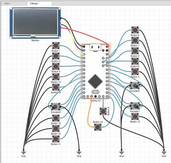
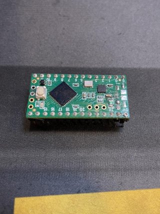
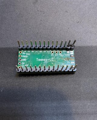
I have a few of the attached Teensy LC boards and wondering if there's a way to reach a trace for the D- pin specifically as my micro B connector broke off taking the D- pad with it somehow and of course I had previously lifted the D- pad on the underside in an entirely separate incident long ago. So my normal 2 routes are gone. I'd like to be able to repair the USB but that seems out so is there any way to solder to a D- somewhere or is this board cooked? I've checked all the traces in a public schematic and couldn't find a clear area but there also is likely something I don't know that might be a simple solution. Attached my wiring for my device too just for reference should that be needed.

Nick

Additional Details:
Hardware: https://www.pjrc.com/store/teensylc.html
Wiring: Attached
 

Attachments

  • Button Box Wiring.jpg
    Button Box Wiring.jpg
    158.6 KB · Views: 22
  • Teensy1.jpg
    Teensy1.jpg
    175.7 KB · Views: 23
  • Teensy2.jpg
    Teensy2.jpg
    216.9 KB · Views: 27
z.png
You could attach wires to the ends of R1 and R2.
Also the D+ and D- seem to go into vias which would also be a good pick up point.
 
Hi BriComp,

Really appreciate the reply. Good catch on R1 & R2! I'll expose the trace and solder into these 2 points in the attached image in red unless you object & i'm overlooking a simpler solution.

As for your recommendation on "vias": I'm not familiar with what you're referring to unfortunately. But after checking the schematic and the forum, I couldn't find any board mark or reference to VIAS. Is there another way to explain it ? Sorry for the dumb question.

Data Taps.jpg
 
Good catch on R1 & R2! I'll expose the trace and solder into these 2 points in the attached image in red unless you object & i'm overlooking a simpler solution.
That's the wrong side of R! and R2. You have chosen to solder between the Resistors and Processor. D+ and D- are on the other side of the resistors.

EDIT:

If you do solder in the place indicated then just add 33R resistors in series with each wire.

Instead of scraping off the solder resist I would have thought that you could solder to the top end of each resistor.
 
Last edited:
Looks like whatever went wrong may have also damaged a wire on the bottom side which provides 3.3V to the bootloader chip. If that wire really is broken, be sure to repair it too.

3volts.jpg
 
That's the wrong side of R! and R2. You have chosen to solder between the Resistors and Processor. D+ and D- are on the other side of the resistors.

EDIT:

If you do solder in the place indicated then just add 33R resistors in series with each wire.

Instead of scraping off the solder resist I would have thought that you could solder to the top end of each resistor.

Another good point - hadn't considered that. Didn't even think there was any solder there though I suppose of course there must be. I'll get some flux and be precise. thank you!
 
Looks like whatever went wrong may have also damaged a wire on the bottom side which provides 3.3V to the bootloader chip. If that wire really is broken, be sure to repair it too.

View attachment 31105

Thanks for the heads up Paul - I hadn't even noticed that interruption. There's still just a pinch of trace left but to your point I'll triple check it's functional as it's pretty close to being severed.
 
Back
Top