Guitar Distortion Effect using waveshape and Teensy 4.0 with Audio Shield

lsrichard

Member
First I would like to thank Kenny Peng for coding the waveshape example that I could build from.
I wanted to experiment with the waveshape effect in Teensy Audio for use with electric guitar and organ.
I found that is was best to test the math I would be using and visualize the shape curves first with the Processing 3 program.
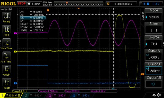
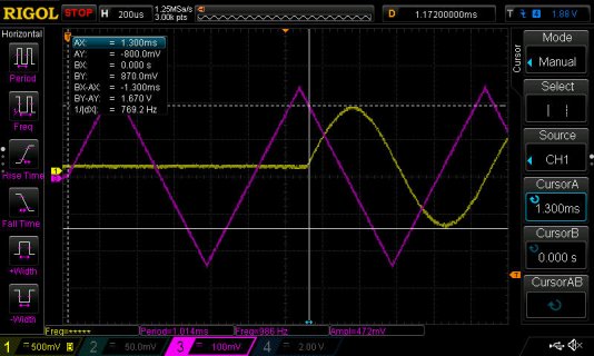
I started with the sin function making a curve shape that is essentially a triangle wave to sine wave converter.
Then I applied the sin function on it self by putting the shape array thru the sin function again.
I continued to do this again up to 8 times.
The result is progressively sharper curves for waveshape.

Quad sin small.jpg

With that done I converted the code to Arduino C for use with the Teensy 4.0 with Audio Shield.
I also added a power supply, a one transistor impedance buffer to the Audio Shield input and true bypass wiring to the circuit of the pedal.

shapepedal.jpg

insideshape.jpg

This actually sounds pretty good for a guitar distortion effect.
It will get progressively more noisy at the higher settings but is still a useful effect.
It has the ability to be clean on most settings as long as you turn down the guitar volume enough and play very lightly or be a heavy lead distortion when you turn it up and play more heavily.
It is also useful on keyboards to give that organ patch a bit of a grind sound.
I will try different algorithms to apply different shapes in the future but this is enough for now.

Code for Arduino:

Code:
// Up to 8 x Sin function for guitar distortion effect

// Thanks to Kenny Peng for making the waveshape example that I could build from

#include <Audio.h> 
#include <Wire.h>
#include <SPI.h>
#include <SD.h>
#include <SerialFlash.h>

// GUItool: begin automatically generated code
AudioInputI2S            i2s1;           //xy=97,52
AudioEffectWaveshaper    waveshape1;     //xy=271,33
AudioEffectWaveshaper    waveshape2;     //xy=271,71
AudioOutputI2S           i2s2;           //xy=436,51
AudioConnection          patchCord1(i2s1, 0, waveshape1, 0);
AudioConnection          patchCord2(i2s1, 1, waveshape2, 0);
AudioConnection          patchCord3(waveshape1, 0, i2s2, 0);
AudioConnection          patchCord4(waveshape2, 0, i2s2, 1);
AudioControlSGTL5000     sgtl5000_1;     //xy=252,111
// GUItool: end automatically generated code

float myWaveshape2[32769]; // array 1 // full sin function 
float fi; // adjusted float version of i int
float ds16 = 8; // 1000 mutiplier of sin function result
float d16; // result of sin function math after multiplier
float dgain = 1; // amplitude of sin function result
const float pi = 3.141592654; // pi
float lg [32769]; // array 2 // re-applied sin function
float fv; // fv for re-aplication of sin function
float knob_A1;// re aplication control knob // 20KB used
float avg_A1;// average of knob
unsigned int n; // counter for averaging ect.
byte smode; // re-application mode 0 to 7 
byte oldsmode; // old smode to check and do NewShape(); only one time after smode changes.

// switch to an analog pot divided down to 0 thru 7 // Use A1 pin 15 analog input with 10kB or 25kB pot
//const int switchPin2 = 2; // pin number switch 2
//const int switchPin3 = 3; // pin number switch 3
//const int switchPin4 = 4; // pin number switch 3
 
void setup() {  
  //Serial.begin(115200); // only needed for serial monitor 
  AudioMemory(12);
  analogReadResolution(12); // read will be 0 to 4095 if set to (12).

  //pinMode(switchPin2, INPUT_PULLUP); // switch 2
  //pinMode(switchPin3, INPUT_PULLUP); // switch 3
  //pinMode(switchPin4, INPUT_PULLUP); // switch 3

  //int reading0 = ! digitalRead(switchPin2);
  //int reading1 = ! digitalRead(switchPin3);
  //int reading2 = ! digitalRead(switchPin4);

  //smode = (reading2 * 4) + (reading1 * 2) + reading0;// three bit 01234567

  knob_A1 = (float)analogRead(A1);// Selector 0 thru 7 divide by 596
  smode = round ( knob_A1 / 596 );// must be rounded and 0 to 7

  NewShape();// this is all that is needed for first setup  
   
  sgtl5000_1.enable();
  sgtl5000_1.lineInLevel(11); // Optimal for 480mV_p-p signal
  sgtl5000_1.lineOutLevel(25); // Under 25 causes soft clipping
  //Serial.print(smode);
}// setup

void loop() {
  knob_A1 = (float)analogRead(A1); // Read 20KB pot
  avg_A1 = avg_A1 + knob_A1; // add for 32 loops
  if ((n & 31) == 31) { // use if ((n & 31) == 31) will average 32 times should be enough // act when (n & 31) == 31 ( 5 bits high ) 
      avg_A1 = avg_A1 / 32; //average of 32 knob readings
      smode = round ( avg_A1 / 596 ); // round and divide down to 0 to 7 for switch function
      avg_A1=0; //reset avg after use     
  } // if (n&31) == 31  
  //ReadSwitches();
  if (smode != oldsmode) NewShape(); // only act if "smode" changed // if conditional so it only do this subroutine one time after "smode" changes
  ++n; // n counter for avg
  n=n & 1023; // 10 bit roll over to 0   
} // MAIN LOOP

void NewShape(void){
  oldsmode = smode; // this is for the if conditional so it only do this subroutine one time after "smode" changes
  for (int i=0; i<32769; i++) { 
    fi = i + 16384; // float needed for math to be correct // 16384 is starting point at top of sine 
    d16 = sin( pi * ( fi / 32768 )) * ( ds16 * 1000 ); // fi/32768 to give middle 1/2 cycle starting the peak of the sine.
    myWaveshape2[i] = round( d16 * dgain ); // round and gain 
    myWaveshape2[i]= -(myWaveshape2[i]/8000); // needed math to divide back to -1.0 to 1.0   
  } //for i

  for (int i=0; i<32769; i++) {
    fv=myWaveshape2[i]*16384; // set fv for re-aplication of sin function
    d16 = sin( pi * ( fv / 32768 )) * ( ds16 * 1000 );// sin function
    lg[i] = round( d16 * dgain ); // round and gain 
    lg[i]= lg[i]/8000; // needed math to divide back to -1.0 to 1.0 
  } // for

//Serial.print(smode);
//Serial.println(reading0);
//Serial.println(reading1);
//Serial.println(reading2);
//Serial.println(smode);

  switch (smode){
    case 0 : // Full sin function
      for (int i=0; i<32769; i++) {
        lg[i]=(myWaveshape2[i]);// just transfer full sin fuction shape  
      } // for      
    break;
     
    case 1 : // Double sin function
      // nothing needed here // really do nothing for case 1 // uses lg[] defalt double sin function shape         
    break;
     
    case 2 : // Triple sin function
      SinReAp();// 3rd re-aplication of sin function   
    break;
     
    case 3 : // Quad sin function
      SinReAp();// 3rd re-aplication of sin function
      SinReAp();// 4th re-aplication of sin function
    break;

    case 4 : // 5x sin function
      SinReAp();// 3rd re-aplication of sin function
      SinReAp();// 4th re-aplication of sin function
      SinReAp();// 5th re-aplication of sin function
    break;
  
    case 5 : // 6x sin function
      SinReAp();// 3rd re-aplication of sin function
      SinReAp();// 4th re-aplication of sin function
      SinReAp();// 5th re-aplication of sin function
      SinReAp();// 6th re-aplication of sin function
    break;
  
    case 6 : // 7x sin function
      SinReAp();// 3rd re-aplication of sin function
      SinReAp();// 4th re-aplication of sin function
      SinReAp();// 5th re-aplication of sin function
      SinReAp();// 6th re-aplication of sin function
      SinReAp();// 7th re-aplication of sin function  
    break;
  
    case 7 : // 8x sin function
      SinReAp();// 3rd re-aplication of sin function
      SinReAp();// 4th re-aplication of sin function
      SinReAp();// 5th re-aplication of sin function
      SinReAp();// 6th re-aplication of sin function
      SinReAp();// 7th re-aplication of sin function
      SinReAp();// 8th re-aplication of sin function
    break;
   
  }// switch
 
waveshape1.shape(lg, 32769);// shape implementation L
waveshape2.shape(lg, 32769);// shape implementation R 
   
  //sgtl5000_1.enable(); // do not need to re-enable // this makes it cut out for a second if used
  //sgtl5000_1.lineInLevel(11); // Optimal for 480mV_p-p signal // no need to re-do
  //sgtl5000_1.lineOutLevel(25); // Under 25 causes soft clipping // no need to re-do
} // NewShape

void SinReAp(void){
  for (int i=0; i<32769; i++) {
    fv=lg[i]*16384; // set fv re-aplication of sin function as many times as needed
    d16 = sin( pi * ( fv / 32768 )) * ( ds16 * 1000 );// sin function 
    lg[i] = round( d16 * dgain ); // round and gain 
    lg[i]= lg[i]/8000; // needed math to divide back to -1.0 to 1.0  
  } // for   
} // SinReAp

//void ReadSwitches(void){
//  int reading0 = ! digitalRead(switchPin2);
//  int reading1 = ! digitalRead(switchPin3);
//  int reading2 = ! digitalRead(switchPin4);

//  smode = (reading2 * 4) + (reading1 * 2) + reading0;// three bit 01234567 // three separate bit binary to byte convert 
//} // ReadSwitches
 

Attachments

  • curve_multi8.ino
    7.3 KB · Views: 37
  • shapecode.txt
    7.3 KB · Views: 45
I am adding the Processing 3 code to visualize the curves i used with waveshape.
Do not compile this code in Adruino without converting it first.
This Code is for Pocessing 3.

Code:
// For Guitar Distortion using Teensy 4.0 with Audio Shield
// Up to 8 x Sin function for guitar distortion effect
// Re-Applied sin function for WaveShape

// Thanks to Kenny Peng for making the waveshape example that I could build from

// NOTE: THIS IS A PROCESSING PROGRAM DO NOT SAVE OR COMPILE IN ARDUINO

// TO CONVERT TO ARDUINO FROM PROCESSING PROGRAM:
 // change array syntax [32769] and no (float [] lg ;)
 // remove path and PShape commands
 // add library links and Audio connections
 // remove secondary array definition from setup
 // add Serial.begin(115200); and AudioMemory(12); to setup
 // remove all "size" commands.
 // remove all "path" commands. 
 // remove "draw()" subroutine.
 // add waveshape1.shape(myWaveshape2, 32769); to end of setup
 // add waveshape2.shape(myWaveshape2, 32769); to end of setup
 // add sgtl5000_1.enable(); to end of setup
 // add sgtl5000_1.lineInLevel(15); to end of setup
 // add sgtl5000_1.lineOutLevel(25); to end of setup
 // add main loop
 
/**
 * PathPShape
 * 
 * A simple path using PShape
 */

// A PShape object
PShape path;
float [] myWaveshape2 ; // array 
float fi;
float ds16 = 8;
float d16;
float dgain = 1;
float pi = 3.141592654; // pi
float [] lg ; // array
int smode = 7;
float fv;

void setup() {
  size(640, 360, P2D);
  myWaveshape2 = new float[32769]; // further define array
  path = createShape(); 
  NewShape();  
} // setup

void draw() {
  delay(2000);
  background(0,0,0); // background color
  path.setStroke(color(0,255,0));// red, green, blue // line color
  translate(50, 150); // location of shape
  shape(path);// draw shape
  textSize(24);
  fill(255, 191, 0);// amber text // text color
  
  switch (smode){
      case 0 :
        NewShape();
        text("Full sin function",110, -125);  
     break; 
      case 1 :
        NewShape();
        text("Double sin function",110, -125); 
      break;
      case 2 :
        NewShape();
        text("Triple sin function",110, -125);  
        break;
      case 3 :
        NewShape();
        text("Quad sin function",110, -125);
      break;
      case 4 :
        NewShape();
        text("x5 sin function",110, -125);  
      break; 
      case 5 :
        NewShape();
        text("x6 sin function",110, -125); 
      break;
      case 6 :
        NewShape();
        text("x7 sin function",110, -125);  
      break;
      case 7 :
        NewShape();
        text("x8 sin function",110, -125);
      break;
  }// switch
  
  textSize(18);
  text("First in array  0", 350, 50);
  text(lg[0], 350, 70);
  text("Last in array 32768",350, 110);
  text(lg[32768], 350, 130);
}// draw

void NewShape(){
  smode++;
  if (smode == 8){
  smode=0;
  }// smode==8
  path.setStroke(color(0,255,0));// red, green, blue // line color
  
  lg = new float[32769];// further define array
  for (int i=0; i<32769; i++) { 
    fi = i + 16384; // float needed for math to be correct // 16384 is starting point at top of sine 
    d16 = sin( pi * ( fi / 32768 )) * ( ds16 * 1000 ); // fi/32768 to give middle 1/2 cycle starting the peak of the sine.
    myWaveshape2[i] = round( d16 * dgain ); // round and gain 
    myWaveshape2[i]= -(myWaveshape2[i]/8000); // needed math to divide back to -1.0 to 1.0   
  } //for i
  for (int i=0; i<32769; i++) {
    fv=myWaveshape2[i]*16384; // set fv for re-aplication of sin function
    d16 = sin( pi * ( fv / 32768 )) * ( ds16 * 1000 );// sin function
    lg[i] = round( d16 * dgain ); // round and gain 
    lg[i]= lg[i]/8000; // needed math to divide back to -1.0 to 1.0 
  } // for 
  
  switch (smode){
    case 0 : // Full sin function
      path = createShape();
      path.beginShape();
      path.noFill();
      path.stroke(255); // brightness of line
      path.strokeWeight(1); // thickness of line
      for (int i=0; i<32769; i++) {
          lg[i]=(myWaveshape2[i]);// just transfer full sin fuction shape 
          path.vertex(i/100,lg[i]*100);// put array into shape named path
          //if (( i & 63 )== 63) {// print every 64th loop
           // print(lg[i]);
           // print(",");
           // if (( i & 511 )== 511)println();
          //}// i & 63 
      } // for 
      path.endShape();     
    break;
     
    case 1 : // Double sin function
      // 3rd re-aplication of sin function
      path = createShape();
      path.beginShape();
      path.noFill();
      path.stroke(255); // brightness of line
      path.strokeWeight(1); // thickness of line
      for (int i=0; i<32769; i++) {
          fv=myWaveshape2[i]*16384; // set fv for re-aplication of sin function
          d16 = sin( pi * ( fv / 32768 )) * ( ds16 * 1000 );// sin function
          lg[i] = round( d16 * dgain ); // round and gain 
          lg[i]= lg[i]/8000; // needed math to divide back to -1.0 to 1.0 
          path.vertex(i/100,lg[i]*100);// put array into shape named path
          //if (( i & 63 )== 63) {// print every 64th loop
            //print(lg[i]);
            //print(",");
            //if (( i & 511 )== 511)println();
          //}// i & 63 
       }// for
      path.endShape();              
    break;
     
    case 2 : // Triple sin function
      SinReAp();// 3rd re-aplication of sin function   
    break;
     
    case 3 : // Quad sin function
      SinReAp();// 3rd re-aplication of sin function
      SinReAp();// 4th re-aplication of sin function
    break;

    case 4 : // 5x sin function
      SinReAp();// 3rd re-aplication of sin function
      SinReAp();// 4th re-aplication of sin function
      SinReAp();// 5th re-aplication of sin function
    break;
  
    case 5 : // 6x sin function
      SinReAp();// 3rd re-aplication of sin function
      SinReAp();// 4th re-aplication of sin function
      SinReAp();// 5th re-aplication of sin function
      SinReAp();// 6th re-aplication of sin function
    break;
  
    case 6 : // 7x sin function
      SinReAp();// 3rd re-aplication of sin function
      SinReAp();// 4th re-aplication of sin function
      SinReAp();// 5th re-aplication of sin function
      SinReAp();// 6th re-aplication of sin function
      SinReAp();// 7th re-aplication of sin function  
    break;
  
    case 7 : // 8x sin function
      SinReAp();// 3rd re-aplication of sin function
      SinReAp();// 4th re-aplication of sin function
      SinReAp();// 5th re-aplication of sin function
      SinReAp();// 6th re-aplication of sin function
      SinReAp();// 7th re-aplication of sin function
      SinReAp();// 8th re-aplication of sin function
    break;
   
  }// switch
 
//waveshape1.shape(lg, 32769);// shape implementation L
//waveshape2.shape(lg, 32769);// shape implementation R 
   
} // NewShape

void SinReAp(){
  path = createShape();
  path.setStroke(color(0,255,0));// red, green, blue // line color
  path.beginShape();  
  path.strokeWeight(1); // thickness of line
  path.noFill();
  
  for (int i=0; i<32769; i++) {
    fv=lg[i]*16384; // set fv re-aplication of sin function as many times as needed
    d16 = sin( pi * ( fv / 32768 )) * ( ds16 * 1000 );// sin function 
    lg[i] = round( d16 * dgain ); // round and gain 
    lg[i]= lg[i]/8000; // needed math to divide back to -1.0 to 1.0
    path.vertex(i/100,lg[i]*100);// put array into shape named path

  //if (( i & 63 )== 63) {// print every 64th loop
    //print(lg[i]);
    //print(",");
  //if (( i & 511 )== 511)println();
  //}// i & 63  
    path.vertex(i/100,lg[i]*100);// put array into shape named path
} // for 
  path.endShape(); 
} // SinReAp
 
Impedance buffer

This attachment is the impedance buffer I used.
It is needed because the audio shield input impedance is 29K ohms and the guitar needs it to be higher than that.
 

Attachments

  • Schematic Design_ impbuff.pdf
    1.1 MB · Views: 76
But it only has about 100k input itself - the 2N3391A's gain is 250 worst case, so the 470 ohm load will be reflected back as low as 117k, in parallel with the bias circuit's 510k resistance gives about 100k. I presume you wanted 500k input impedance for the guitar? A simple opamp follower is good way to buffer a high impedance signal.
 
You got me curious about what input impedance I was actually getting so I measured it with my scope, generator and a 1 meg pot.
At 1KHz I measured it at 439k ohms. That buffer circuit should be able to have 446k ohms input impedance but that is close enough for me.
 
Guess you are lucky with the actual gain of those transistors then - I'd have just gone with an opamp in non-inverting mode which has very high input impedance.
 
@Isrichard Cool effect! I listened to the Soundcloud recording. I do hear a fair bit of click/clip noise when I listen through headphones. But, it's hard to say if the input to the ADC is clipping, or the digital audio processing is having little jumps that exceed Nyquist.

For anyone reading this that may be interested, an easy preamp design is to use a TL072 JFET, with split 1M (to get 500K) or split 2M (to get 1M) input impedance. See the schematic on page 20 for a reference.
https://d3s5r33r268y59.cloudfront.n...6-13-11-39/TGA_Pro_MKII_User_Guide_-_v2.2.pdf

The same preamp design is used in the Teensy based Multiverse. Consider with guitar inputs, you might need a decent amount of gain (passive pickups) to get to the 1vpp for the typical codec, or you might need attenuation if you've got active pickups, or go through a 9V pedal first.
 
New more extensive rough video demo

One of my repair customers requested to try out the waveshape pedal here at my shop.
He liked it enough to video it with his phone.
We ended up making a Youtube video of a more extensive rough demo of the pedal.

https://youtu.be/acdpXPj55K4
 
I used my scope and generator to do a latency measurement.
Its latency measured at 6.38ms.

https://forum.pjrc.com/attachment.php?attachmentid=31252&d=1686190142&thumb=1&stc=1

6ms is a bit high if you are mixing in a dry signal elsewhere. If you want to reduce the latency cut the number of samples in an audio block down from the default 128.

Edit .../cores/teensy4/AudioStream.h and change AUDIO_BLOCK_SAMPLES to 16, recompile and re-measure the latency

cheers, Paul
 
@Isrichard - changing AUDIO_BLOCK_SAMPLES shouldn't change the way the pedal behaves or the sound of your effect at all (other than latency).

By default the library processes sound in blocks of 128 samples (128 samples at 44.1kHZ = 2.9ms) reducing this just means that audio is processed in smaller chunks (16 samples = 0.3ms). It adds a bit of processing overhead but a teensy 4 has lots of capacity for processing. Most of the objects in the library work with reduced blocks and if they don't they normally fail very noticeably (the only one I've come across that doesn't work well with it is the USB Audio out, there may be others that fail that I haven't come across). Cheers, Paul
 
AudioStream.h lists following as problematic with lower block sizes

- AudioInputUSB, AudioOutputUSB, AudioPlaySdWav, AudioAnalyzeFFT256, AudioAnalyzeFFT1024
 
Interesting stuff. I knew distortion had to do with clipping and going through an s-curve wave shaper.
Reading through different pedal dissection forums, this s-curve is the caracterisation of the pedal. Many have their curve off-centered and gives them a particular sound. I was thinking that instead of computing the curve with sin formulae, it could have a caracterisation code that send a signal to the pedal and read its output. This way, it could be possible to "clone" a distortion effect.
Anybody ever tried that?

And also, we need anti aliasing.
I also learning about distortion.
No good result so far.
 
Every non-linearity introduces new harmonics. You should do Taylor series expansion to see what is the amplitude of components generated. For example single sine gets expanded to
sin(x) = x − x^3/3! + x^5/5! − x^7/7! + · · ·

Each power component of Nth degree creates Nth harmonic. So x^3 term would create third harmonic.

So you have infinite harmonics by going thru one sin() waveshaper. That causes heavy aliasing. 3rd harmonic has amplitude of 1/6 (-15dB), 5th harmonic 1/120 (-41dB). If you want the effect to work properly you need to heavily oversample BEFORE applying waveshaper. I would oversample at least 8x or better yet 16x. Proper oversampling requires running polyphase FIR filter. https://www.mathworks.com/help/dsp/ref/firinterpolation.html

Also (as optimization technique) you can use Taylor expansion instead of sine function calls. Calculating polynomials is way faster as it is just few multiplications and additions. Another thing that I noticed in your code is that you are using sin() - that is DOUBLE (64-bit) function. You should be using sinf() - single precision (32-bit) floating point function that is way faster and perfectly enough for audio.
 
Last edited:
Every non-linearity introduces new harmonics. You should do Taylor series expansion to see what is the amplitude of components generated. For example single sine gets expanded to
sin(x) = x − x^3/3! + x^5/5! − x^7/7! + · · ·

Each power component of Nth degree creates Nth harmonic. So x^3 term would create third harmonic.

So you have infinite harmonics by going thru one sin() waveshaper. That causes heavy aliasing. 3rd harmonic has amplitude of 1/6 (-15dB), 5th harmonic 1/120 (-41dB). If you want the effect to work properly you need to heavily oversample BEFORE applying waveshaper. I would oversample at least 8x or better yet 16x. Proper oversampling requires running polyphase FIR filter. https://www.mathworks.com/help/dsp/ref/firinterpolation.html

Also (as optimization technique) you can use Taylor expansion instead of sine function calls. Calculating polynomials is way faster as it is just few multiplications and additions. Another thing that I noticed in your code is that you are using sin() - that is DOUBLE (64-bit) function. You should be using sinf() - single precision (32-bit) floating point function that is way faster and perfectly enough for audio.

Do you have any available example of anti aliasing method( e.g. Oversampling> filter> hardclip> filter> downsampling) .I am still struggling to learn.
 
Back
Top