Forum Rule: Always post complete source code & details to reproduce any issue!
Results 1 to 18 of 18

Thread: Teensy 4.1 usbmidi to cv !

  1. #1

    Teensy 4.1 usbmidi to cv !

    Hi ! Trying to make a midi to cv with my teensy 4.1 with a MPC4822 DAC.

    From now, I believe the teensy receive the messages but the outputs of the 4822 are only +- 0.5v at maximum and doesnt really follow my automations.

    I feed the Dac with the 5v of the teensy.

    Board set to midix4, 600mhz, fastest.

    Here's my code :

    #include <MIDI.h>
    #include <SPI.h>

    // Define the MIDI channel and CC number you want to use for CV output
    const int midiChannel = 1; // MIDI channel (1-16)
    const int ccNumber = 39; // Control Change (CC) number (0-127)

    // Define the CV output pin
    const int cvOutputPin = 16; // Digital pin number (0-39) on Teensy 4.1

    // Define MCP4822-related pins
    const int chipSelectPin = 10; // Chip select (CS) pin
    const int dataOutPin = 11; // SPI MOSI pin
    const int clockPin = 13; // SPI clock pin

    MIDI_CREATE_INSTANCE(HardwareSerial, Serial1, MIDI);

    void setup() {
    // Initialize the CV output pin
    pinMode(cvOutputPin, OUTPUT);

    // Initialize MCP4822-related pins
    pinMode(chipSelectPin, OUTPUT);

    // Initialize SPI communication
    SPI.begin();
    SPI.beginTransaction(SPISettings(16000000, MSBFIRST, SPI_MODE0)); // Adjust the SPI clock speed if needed

    // Initialize the MIDI interface
    Serial1.begin(31250); // Set baud rate for MIDI communication
    MIDI.begin(MIDI_CHANNEL_OMNI); // Set MIDI channel mode to Omni

    // Set up MIDI CC callback function
    MIDI.setHandleControlChange(OnControlChange);
    }

    void loop() {
    // Process incoming MIDI messages
    MIDI.read();
    }

    void OnControlChange(unsigned char channel, unsigned char control, unsigned char value)
    {
    // Check if the received MIDI message matches the specified CC number and channel
    if (control == ccNumber && channel == midiChannel) {
    // Map the CC value (0-127) to the desired CV range (e.g., 0-4095)
    uint16_t cvValue = map(value, 0, 127, 0, 4095);

    // Output the CV value to the MCP4822 chip
    digitalWrite(chipSelectPin, LOW); // Enable MCP4822 communication

    // Construct the 16-bit value to be sent to the MCP4822
    uint16_t spiData = 0b0111000000000000 | (cvValue & 0b0000111111111111);

    // Send the data to the MCP4822
    SPI.transfer16(spiData);

    digitalWrite(chipSelectPin, HIGH); // Disable MCP4822 communication
    }
    }


    Im really not into code im trying to make music haha

    If someone made one already and have a clue that would be incredible!

    Thanks a lot !

  2. #2
    Senior Member PaulStoffregen's Avatar
    Join Date
    Nov 2012
    Posts
    28,468
    As a first troubleshooting step, I'd recommend printing to the Arduino Serial Monitor so you can see the actual number before your code tries to send it to the MCP4822.

    Something like this:

    Code:
      // Map the CC value (0-127) to the desired CV range (e.g., 0-4095)
      uint16_t cvValue = map(value, 0, 127, 0, 4095);
      Serial.println(cvValue);

  3. #3
    Ok i'll try that !

  4. #4
    Ok so i dont know if this would be the proper way to do it but i add that serial print code in the loop of my code then upload into teensy. After i started Logic with my automation and then open the serial monitor but nothing is shown there.
    Does this mean it even receive no cc ? Thanks !

  5. #5
    Senior Member PaulStoffregen's Avatar
    Join Date
    Nov 2012
    Posts
    28,468
    Add this at the end of setup(). Or anywhere in setup()...

    Code:
      Serial.begin(9600);
      while (!Serial) ; // wait for Arduino Serial Monitor
      Serial.println("Hello World");
    This won't fix anything, but it will at least confirm if Serial.println() is really sending to the Arduino Serial Monitor window.

  6. #6
    Senior Member PaulStoffregen's Avatar
    Join Date
    Nov 2012
    Posts
    28,468
    When you see it print Hello World, the next step is to add something like this:

    Code:
    void OnControlChange(unsigned char channel, unsigned char control, unsigned char value)
    {
      Serial.println("received CC message");
    so you can tell if any CC messages are really arriving. This can tell you if your input circuitry is working. No point messing with the software side if the input circuit is bad.

    You can also add printing of their parameters, if that helps to figure why messages you are getting don't give the expected result.

  7. #7
    It writes Hello world at the start. Then I add the next code to print cc message in the loop but nothing again !

    This is the code from now :

    #include <MIDI.h>
    #include <SPI.h>

    // Define the MIDI channel and CC number you want to use for CV output
    const int midiChannel = 1; // MIDI channel (1-16)
    const int ccNumber = 39; // Control Change (CC) number (0-127)

    // Define the CV output pin
    const int cvOutputPin = 16; // Digital pin number (0-39) on Teensy 4.1

    // Define MCP4822-related pins
    const int chipSelectPin = 10; // Chip select (CS) pin
    const int dataOutPin = 11; // SPI MOSI pin
    const int clockPin = 13; // SPI clock pin

    MIDI_CREATE_INSTANCE(HardwareSerial, Serial1, MIDI);

    void setup() {
    // Initialize the CV output pin
    pinMode(cvOutputPin, OUTPUT);

    // Initialize MCP4822-related pins
    pinMode(chipSelectPin, OUTPUT);

    // Initialize SPI communication
    SPI.begin();
    SPI.beginTransaction(SPISettings(16000000, MSBFIRST, SPI_MODE0)); // Adjust the SPI clock speed if needed

    // Initialize the MIDI interface
    Serial1.begin(31250); // Set baud rate for MIDI communication
    MIDI.begin(MIDI_CHANNEL_OMNI); // Set MIDI channel mode to Omni

    // Set up MIDI CC callback function
    MIDI.setHandleControlChange(OnControlChange);

    Serial.begin(9600);
    while (!Serial) ; // wait for Arduino Serial Monitor
    Serial.println("Hello World");
    }

    void loop() {
    // Process incoming MIDI messages
    MIDI.read();
    }

    void OnControlChange(unsigned char channel, unsigned char control, unsigned char value)
    {

    Serial.println("received CC message");
    // Check if the received MIDI message matches the specified CC number and channel
    if (control == ccNumber && channel == midiChannel) {
    // Map the CC value (0-127) to the desired CV range (e.g., 0-4095)
    uint16_t cvValue = map(value, 0, 127, 0, 4095);

    // Output the CV value to the MCP4822 chip
    digitalWrite(chipSelectPin, LOW); // Enable MCP4822 communication

    // Construct the 16-bit value to be sent to the MCP4822
    uint16_t spiData = 0b0111000000000000 | (cvValue & 0b0000111111111111);

    // Send the data to the MCP4822
    SPI.transfer16(spiData);

    digitalWrite(chipSelectPin, HIGH); // Disable MCP4822 communication
    }

    // Map the CC value (0-127) to the desired CV range (e.g., 0-4095)
    uint16_t cvValue = map(value, 0, 127, 0, 4095);
    Serial.println(cvValue);

    }

    Thanks !

  8. #8
    Senior Member PaulStoffregen's Avatar
    Join Date
    Nov 2012
    Posts
    28,468
    In Arduino, click File > Examples > Teensy > Serial > EchoBoth. Change the baud rate from 38400 to 31250 and upload.

    Optional, add the Hello World stuff, so you can be sure it is really running.

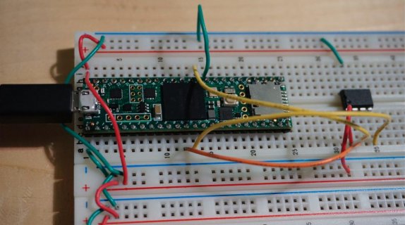
    Does it print anything at all while your MIDI messages are incoming? If nothing, then you probably have a hardware issue with the MIDI input circuitry. We can help, but only if we're able to see it. Photos are best...

  9. #9
    I understand ! So I did what you said , Hello world appeared ! But yea no midi cc..

    On thing is each time i upload, Logic give me a notification that its see the 4 midi i/o so i believe the midi implementation is working ! Well I hope haha

  10. #10
    Click image for larger version. 

Name:	Screen Shot 2023-05-31 at 7.10.43 PM.jpg 
Views:	5 
Size:	94.9 KB 
ID:	31209 The actual set up !

  11. #11
    So the inputs are via usb !

  12. #12
    Senior Member PaulStoffregen's Avatar
    Join Date
    Nov 2012
    Posts
    28,468
    Your program is using the MIDI library, which receives ordinary serial MIDI (5 pin DIN connector).

    To receive USB MIDI from your computer over the USB cable, use "usbMIDI". Documentation here:

    https://www.pjrc.com/teensy/td_midi.html

    You can also try running File > Examples > Teensy > USB_MIDI > InputRead.

  13. #13
    Oh ayaye haha I though because of the Midix4 set up it would communicate ! Thanks for your help! Ill try another one Have a good day !

  14. #14
    Ok ! So back on track with another take ! Things seems to be going good except that I cannot get the 4822 to deliver 5v at 127 value.
    But it follows the automation ( maybe it could be faster but will see that later )

    Here's the code:

    #include <SPI.h>


    // Define the MIDI channel and CC number you want to use for CV output
    const int midiChannel = 1; // MIDI channel (1-16)
    const int ccNumber = 20; // Control Change (CC) number (0-127)

    // Define the CV output pin
    const int cvOutputPin = 16; // Digital pin number (0-39) on Teensy 4.1

    // Define MCP4822-related pins
    const int chipSelectPin = 10; // Chip select (CS) pin
    const int dataOutPin = 11; // SPI MOSI pin
    const int clockPin = 13; // SPI clock pin

    void setup() {
    // Initialize the CV output pin
    pinMode(cvOutputPin, OUTPUT);

    // Initialize MCP4822-related pins
    pinMode(chipSelectPin, OUTPUT);

    // Initialize SPI communication
    SPI.begin();
    SPI.beginTransaction(SPISettings(16000000, MSBFIRST, SPI_MODE0)); // Adjust the SPI clock speed if needed

    // Start USB MIDI communication
    usbMIDI.begin();

    // Set up MIDI CC callback function
    usbMIDI.setHandleControlChange(OnControlChangeWrap per);


    }

    void loop() {
    // Check for incoming USB MIDI messages
    usbMIDI.read();
    }

    void OnControlChangeWrapper(byte channel, byte control, byte value) {
    // Convert data types and call the actual OnControlChange function
    OnControlChange(channel, control, value);
    }

    void OnControlChange(byte channel, byte control, byte value) {
    // Check if the received MIDI message matches the specified CC number and channel
    if (control == ccNumber && channel == midiChannel) {
    // Map the CC value (0-127) to the desired CV range (e.g., 0-4095)
    uint16_t cvValue = map(value, 0, 127, 0, 4095);

    // Output the CV value to the MCP4822 chip
    digitalWrite(chipSelectPin, LOW); // Enable MCP4822 communication

    // Construct the 16-bit value to be sent to the MCP4822
    uint16_t spiData = 0b0111000000000000 | (cvValue & 0b0000111111111111);

    // Send the data to the MCP4822
    SPI.transfer16(spiData);

    digitalWrite(chipSelectPin, HIGH); // Disable MCP4822 communication

    }
    }

    Im about to add an op amp to get the 5v or would it be simpler ( codewise ) to get a 4922/21 ( with a voltage ref ) to achieve the 5v ? Or is there a way to get the 5v with the 4822 just in modifying this code ?

    Thanks a lot !

  15. #15
    Senior Member BriComp's Avatar
    Join Date
    Apr 2014
    Location
    Cheltenham, UK
    Posts
    1,376
    Code:
    #include <SPI.h>
    
    // Define the MIDI channel and CC number you want to use for CV output
    const int midiChannel = 1; // MIDI channel (1-16)
    const int ccNumber = 20; // Control Change (CC) number (0-127)
    
    // Define the CV output pin
    const int cvOutputPin = 16; // Digital pin number (0-39) on Teensy 4.1
    
    // Define MCP4822-related pins
    const int chipSelectPin = 10; // Chip select (CS) pin
    const int dataOutPin = 11; // SPI MOSI pin
    const int clockPin = 13; // SPI clock pin
    
    void setup() {
    	// Initialize the CV output pin
    	pinMode(cvOutputPin, OUTPUT);
    
    	// Initialize MCP4822-related pins
    	pinMode(chipSelectPin, OUTPUT);
    
    	// Initialize SPI communication
    	SPI.begin();
    	SPI.beginTransaction(SPISettings(16000000, MSBFIRST, SPI_MODE0)); // Adjust the SPI clock speed if needed
    
    	// Start USB MIDI communication
    	usbMIDI.begin();
    
    	// Set up MIDI CC callback function
    	usbMIDI.setHandleControlChange(OnControlChangeWrapper);
    }
    
    void loop() {
    	// Check for incoming USB MIDI messages
    	usbMIDI.read();
    }
    
    void OnControlChangeWrapper(byte channel, byte control, byte value) {
    	// Convert data types and call the actual OnControlChange function
    	OnControlChange(channel, control, value);
    }
    
    void OnControlChange(byte channel, byte control, byte value) {
    	// Check if the received MIDI message matches the specified CC number and channel
    	if (control == ccNumber && channel == midiChannel) {
    		// Map the CC value (0-127) to the desired CV range (e.g., 0-4095)
    		uint16_t cvValue = map(value, 0, 127, 0, 4095);
    
    		// Output the CV value to the MCP4822 chip
    		digitalWrite(chipSelectPin, LOW); // Enable MCP4822 communication
    
    		// Construct the 16-bit value to be sent to the MCP4822
    		uint16_t spiData = 0b0111000000000000 | (cvValue & 0b0000111111111111);
    
    		// Send the data to the MCP4822
    		SPI.transfer16(spiData);
    
    		digitalWrite(chipSelectPin, HIGH); // Disable MCP4822 communication
    
    	}
    }
    Hi, glad you are making some progress.
    In future when you are posting code could you enclose it between CODE tags (can be entered by using the # on the reply form) it makes your code easier to read and help those who might be able to help you.

  16. #16
    Oh totally understand ! Sorry for that i didn't know ! Thank you so much

  17. #17
    Senior Member PaulStoffregen's Avatar
    Join Date
    Nov 2012
    Posts
    28,468
    Quick look at the MCP4822 datasheet says it has an internal 2.048V reference, and you can select either unity gain or 2X gain output. So the output range ought to be 0 to 2.048V or 0 to 4.096V. Does not seem to be any way to get 0 to 5V output. You could add an opamp circuit to amplify the voltage.

    If you use a different chip that takes an external reference voltage, check the specs on the DAC and the VREF chip. Often chips need power that at a higher voltage to output their maximum. Most Opamps also have this requirement.

  18. #18
    Ok ! that explain why ! Thanks i'll get my eyes on it

Posting Permissions

  • You may not post new threads
  • You may not post replies
  • You may not post attachments
  • You may not edit your posts
  •