Forum Rule: Always post complete source code & details to reproduce any issue!
Results 1 to 13 of 13

Thread: Teensy4.1 special features + additional pins

  1. #1
    Junior Member
    Join Date
    Mar 2023
    Posts
    7

    Teensy4.1 special features + additional pins

    Hello!

    I have a general question about the 55 I/O pins on the Teensy4.1. I see on the back of the board and pin layout that there are additional pins. But these pins look like they are for traced to specific modules like the SD card and QSPI memory. If I do not want to use these modules and just need extra I/O pins, can I just solder wires them and use them in the program like I would with the other I/O pins on the top side of the board?

    Thank you!

  2. #2
    Senior Member+ KurtE's Avatar
    Join Date
    Jan 2014
    Posts
    11,794
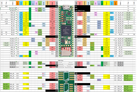
    Yes you can use those other pins for GPIO stuff.

    From my Excel document on T4.x I have the page:
    Click image for larger version. 

Name:	Screenshot.png 
Views:	43 
Size:	388.3 KB 
ID:	31214
    Which shows those pins. are in these areas. For SD, at one point I made a simple plug in circuit board that broke those out. Sparkfun also sells some as well.

  3. #3
    Senior Member
    Join Date
    Feb 2020
    Posts
    170
    Kurt, can you post a link to the spreadsheet? I must have an old version it doesn't have this view.

  4. #4

  5. #5

  6. #6
    Senior Member
    Join Date
    Feb 2020
    Posts
    170
    thanks Kurt

  7. #7
    Junior Member
    Join Date
    Mar 2023
    Posts
    7
    Thank you I will reference this as I program the board.

  8. #8
    Senior Member+ MichaelMeissner's Avatar
    Join Date
    Nov 2012
    Location
    Ayer Massachussetts
    Posts
    4,461
    One thing you might have to be careful about are pins 48-54 that are used for soldering in either 2 PSRAM chips, or 1 PSRAM chaip and 1 flash memory chip. I believe the Teensy initialization functions (called before setup) does a SPI operation to see if there is a PSRAM or flash memory chip attached, and it sets it up if the chips are attached. That SPI operation may confuse any other devices connected to those pins.

  9. #9
    Junior Member
    Join Date
    Mar 2023
    Posts
    7
    Quote Originally Posted by MichaelMeissner View Post
    One thing you might have to be careful about are pins 48-54 that are used for soldering in either 2 PSRAM chips, or 1 PSRAM chaip and 1 flash memory chip. I believe the Teensy initialization functions (called before setup) does a SPI operation to see if there is a PSRAM or flash memory chip attached, and it sets it up if the chips are attached. That SPI operation may confuse any other devices connected to those pins.
    I greatly appreciate your response as this was one of my concerns about the additional pins. I wasn't sure if they are programmed to look for a specific module on startup.

  10. #10
    Junior Member
    Join Date
    Mar 2023
    Posts
    7
    After looking at the pins a bit more, I understand they are only 3.3V tolerant. Sometimes I measure 3.4V when I initialize pullups, but that could just be the volt meter's inaccuracy. Will it be a okay if I have a small pump that sends a signal to the Teensy with a max signal voltage of 3.5V 100mA? I am supplying this small pump with 5V, and the specs state the signals VoutMAX = Vs - 1.5. So mathematically 3.5V is a possible voltage going to the Teensy board's pin. I just wonder if 3.5V will be okay on the pins in the long run.

    IF not, I was planning on using a voltage divider with R1=500ohms and R2=10kOhms to bring 3.5V down to 3.3V.

  11. #11
    Senior Member PaulStoffregen's Avatar
    Join Date
    Nov 2012
    Posts
    28,473
    Using the resistors would be safest.

  12. #12
    Junior Member
    Join Date
    Mar 2023
    Posts
    7
    Quote Originally Posted by MichaelMeissner View Post
    One thing you might have to be careful about are pins 48-54 that are used for soldering in either 2 PSRAM chips, or 1 PSRAM chaip and 1 flash memory chip. I believe the Teensy initialization functions (called before setup) does a SPI operation to see if there is a PSRAM or flash memory chip attached, and it sets it up if the chips are attached. That SPI operation may confuse any other devices connected to those pins.
    Is there a guide on how to reconfigure this software initialization call because currently I am not using PSRAM chips and flash memory chips.

  13. #13
    Senior Member+ defragster's Avatar
    Join Date
    Feb 2015
    Posts
    17,435
    Quote Originally Posted by MichaelMeissner View Post
    One thing you might have to be careful about are pins 48-54 that are used for soldering in either 2 PSRAM chips, or 1 PSRAM chaip and 1 flash memory chip. I believe the Teensy initialization functions (called before setup) does a SPI operation to see if there is a PSRAM or flash memory chip attached, and it sets it up if the chips are attached. That SPI operation may confuse any other devices connected to those pins.
    That seems localized to: FLASHMEM void configure_external_ram() in startup.c.

    Wondering if making that a 'weak' function would allow a sketch to stop the pin chatter searching for PSRAM. Seems it does this one line when no PSRAM found - not sure if that would need to be replicated?
    > memset(&extmem_smalloc_pool, 0, sizeof(extmem_smalloc_pool));

Posting Permissions

  • You may not post new threads
  • You may not post replies
  • You may not post attachments
  • You may not edit your posts
  •