graydetroit
Well-known member
Hi, I'm building a music sequencer device using the Teensy 4.1, and I'm really confused about an issue I'm encountering involving power delivery (I think) when using JST cables vs. typical Dupont cables.
Project info:
- The project uses various components: a 2.42 SSD1309 OLED display (SPI), a TLC5947 powering 22 LEDs, 28 switches (matrixed), capacitive sensing contacts, 4 dual-channel DACs.
- The project is a multi-board project that requires some sort of wired connection between the main (bigger) board and the I/O (smaller) board.
- The I/O board is the one which the Teensy is mounted to.
- The Teensy is powered externally by 5V via a Recom 78E5.0-0.5 dc/dc converter, which is powered by a Recom 78E12-0.5 dc/dc converter, which is in turn powered by a mains wall wart. This is so I can have +12V, +5V, and +3.3V signals for various components I'm using.
- For now, since I'm prototyping, I'm just using 90-degree pin headers and JST and/or dupont connectors to test the connections between the main and I/O boards.
Problem:
I put together a simple test program which cycles through all the LEDs and then runs the Adafruit example OLED graphics example code. When connecting the I/O board power and ground signals to the main board using a 4-pin JST connector, it seems as though the Teensy gets stuck in a restart loop. The OLED and LEDs turn on and the Teensy's LED all hang for a second, and then everything shuts off and the cycle repeats.
However, when connecting the I/O board power and ground signals to the main board using typical Dupont connectors, the program runs fine. The JST connector is oriented correctly, so it's not a matter of it being reversed or anything like that.
Here are two videos showing this issue:
First video -- using the JST connector (data sheet here).
Second video -- using the Dupont connectors.
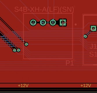
Here is a picture of the I/O board 4-pin section (top view):

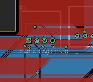
Here is a picture of the main board 4-pin section (top view):

Since this is a multi-board layout, I'm hesitant to share the actual schematics. I can if need be. But I'm wondering if the problem is something easily identifiable just by observing the behavior. I was thinking maybe it's due to the JST connector somehow allowing _too much_ current to be consumed causing the Teensy to restart, while the Dupont connectors are possible limiting the current a bit more? Maybe I need to limit the current that the LEDs consume via the current-limiting resistor used by the TLC5947 (currently using a 5.1k resistor)?
Thanks so much in advance for any help.
Project info:
- The project uses various components: a 2.42 SSD1309 OLED display (SPI), a TLC5947 powering 22 LEDs, 28 switches (matrixed), capacitive sensing contacts, 4 dual-channel DACs.
- The project is a multi-board project that requires some sort of wired connection between the main (bigger) board and the I/O (smaller) board.
- The I/O board is the one which the Teensy is mounted to.
- The Teensy is powered externally by 5V via a Recom 78E5.0-0.5 dc/dc converter, which is powered by a Recom 78E12-0.5 dc/dc converter, which is in turn powered by a mains wall wart. This is so I can have +12V, +5V, and +3.3V signals for various components I'm using.
- For now, since I'm prototyping, I'm just using 90-degree pin headers and JST and/or dupont connectors to test the connections between the main and I/O boards.
Problem:
I put together a simple test program which cycles through all the LEDs and then runs the Adafruit example OLED graphics example code. When connecting the I/O board power and ground signals to the main board using a 4-pin JST connector, it seems as though the Teensy gets stuck in a restart loop. The OLED and LEDs turn on and the Teensy's LED all hang for a second, and then everything shuts off and the cycle repeats.
However, when connecting the I/O board power and ground signals to the main board using typical Dupont connectors, the program runs fine. The JST connector is oriented correctly, so it's not a matter of it being reversed or anything like that.
Here are two videos showing this issue:
First video -- using the JST connector (data sheet here).
Second video -- using the Dupont connectors.
Here is a picture of the I/O board 4-pin section (top view):

Here is a picture of the main board 4-pin section (top view):

Since this is a multi-board layout, I'm hesitant to share the actual schematics. I can if need be. But I'm wondering if the problem is something easily identifiable just by observing the behavior. I was thinking maybe it's due to the JST connector somehow allowing _too much_ current to be consumed causing the Teensy to restart, while the Dupont connectors are possible limiting the current a bit more? Maybe I need to limit the current that the LEDs consume via the current-limiting resistor used by the TLC5947 (currently using a 5.1k resistor)?
Thanks so much in advance for any help.

