KurtE
Senior Member+
- Joined
- Last seen
- Viewing latest content
- Messages
- 12,112
- Reaction score
- 184
Latest activity Postings About
-
-
 KurtE replied to the thread Call to arms | Teensy + SDRAM = true.I can understand the concern about 5v pins... But we have had this issue with every 3.3v only teensy for awhile now. Also ditto for all of the 3.3v Arduino boards, like: the UNO R4 and GIGA But they all have a common setup. Note the UNO is...
 -
-
Wasn't seeing an issue - just a note ... from prior posts some will make boards and some plug wire arrays. Even an ideal total rework couldn't make it 'perfect' for all given potential uses and MEGA class pin count. And any rework has risk.
-
Not sure what the issue is - to be honest I been bringing out the 5V pin to edge connectors on my T4.x and T3x breakouts without an issue as well as other boards I have done. Just have to be careful with the wiring and check the traces before...
-
For now, I've decided to test @jmarsh's second option: make my class a derivative of EventResponder and override EventResponder.triggerevent. I think it has several advantages: 1. Minimal changes to source and no significant change in object...
-
KurtE replied to the thread Highly optimized ILI9341 (320x240 TFT color display) library.@bboyes - Good idea... If the problem is with the display. As I mentioned in previous post, could not tell if he is having the issue with the display or with the SD... If it is the SD, then it may depend on which library he is using... But...
-
KurtE reacted to bboyes's post in the thread Highly optimized ILI9341 (320x240 TFT color display) library with
 Like.
Try bumping SPI clock down to 10 MHz. I seem to recall that the SPI clock was set higher than the data sheet for many displays would support. But that memory may not be reliable. We made a buffered/differential display interface design...
Like.
Try bumping SPI clock down to 10 MHz. I seem to recall that the SPI clock was set higher than the data sheet for many displays would support. But that memory may not be reliable. We made a buffered/differential display interface design... -
KurtE replied to the thread Making the FlexIO_t4 library more Teensy 4.x board independent..The only thing it changes is how it does the map... Also I started from version where I removed the pin information from the hardware structure to a pin info structure... I could have done either way and made the pin info setup for 32...
-
KurtE posted the thread Making the FlexIO_t4 library more Teensy 4.x board independent. in General Discussion.With the currently released version of this library. Each time PJRC releases support for another Teensy 4.x board, the tables within this library (like many others) needed to be updated. This also has issue if someone wishes to make a custom...
-
Yep Milli’s and micros are correct. Display is in millis
-
KurtE replied to the thread Highly optimized ILI9341 (320x240 TFT color display) library.Sorry, hard to know what is going on. How is your display hooked up? In particular, to some circuit board where hopefully you have reasonably short connections, or with breadboard and jumper wires? Would help to see what code you are trying...
-
are the Miilis Micros labels correct? This would be 1,000 times faster? Capture time (millis): 210 PXP time(micros) : 204 No units on : Display time: 232
-
KurtE replied to the thread T4 Pixel Pipeline Library.It works... It is interesting that the PXP takes almost as much time as either the capture or the display Not DMA Finished reading frame Capture time (millis): 210, PXP time(micros) : 204, Display time: 232 PXP rotation 2...
-
-
Actually there is. There are 2 rules of thumb. The source buffer needs to be the image size and The destination buffer should be the display size so in this case if you set your buffers like this for an ILI9488 display: uint8_t s_fb[(640) * 480]...
-
KurtE replied to the thread T4 Pixel Pipeline Library.Hi I tried the new sketch with the HM0360 reading qvga on MMOD and doing the conversion to RGB and rotation. It worked :D I tried changing to VGA and as I sort of expected, not enough memory... Wondering if I can setup the camera to support...
-
Ok pushed the changes mentioned up to my fork of lib and updated the examples if anyone wants to try it https://github.com/mjs513/T4_PXP/tree/pxp_t4_mods The basic calling function is now (included the option for byte swap): void...
-
using the non_camera sketch (another_pxp_test.ino) which just loads images from progmem I did some more timing tests. Based on using 198Mhz for SDRAM clock: Using flexio_teensy_mm image from @Rezo...
-
KurtE replied to the thread Call to arms | Teensy + SDRAM = true.AFAIK... :D Sorry, I should have looked it up, but was at car dealer having service done and replying on phone...
-
Thanks. Been at it again. Since its the set of functions I am using all the time I just created a new one that I am testing. This way don't have to keep copying and pasting code PXP_ps_output(tft.width(), tft.height(), /* Display...
-
KurtE replied to the thread T4 Pixel Pipeline Library.Looks great!
-
Right now this is all on internal buffers on the T4.1 and Micromod. The T41 is using EXTRAM running at 132mhz with a ILI9488 on SPI At some point soonish going to try on SDRAM board.
-
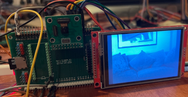
Ok just managed to get do a color conversion from Y8/Y4 to RGB565. That will address issues with HM01B0 and HM0360 cameras - so everything can be done from PXP now. Image from conversion:
-
KurtE replied to the thread Teensy 4.1 - Internal Equivalent Schematic of Digital I/O Pins.I assume you downloaded the IMXRT reference manual as well as the datasheet from the Teensy 4.1 product page? https://www.pjrc.com/store/teensy41.html#tech My guess is that if the information is not contained in these documents, you may need to...
-
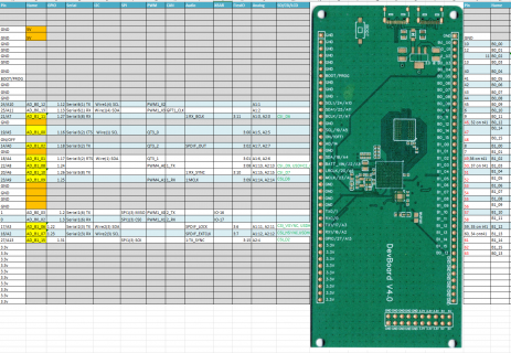
@defragster put that (or adding a single 90° Cross row) out wondering if the denser pin presentation would better fit 100mm (?) limit on low cost 'machine made' boards and limit the wire length for physical wires as well. The (image above...
-
KurtE replied to the thread Call to arms | Teensy + SDRAM = true.I can argue both ways and sometimes I even answer myself 😆 like, larger boards like this where the pin locations are sort of random implies long tangled jumpers, which I get tired of fighting , so end up making shields. Larger boards, more...
-
Double rows would make it more difficult to connect basically anything besides another machine-made board, please don't do that.
-
I agree = double rows would probably make it more difficult to connect a adapter shield
-
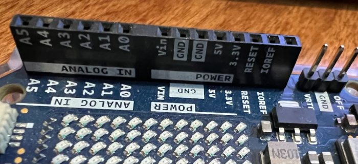
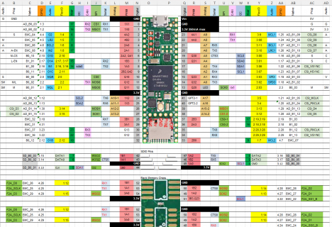
KurtE replied to the thread Call to arms | Teensy + SDRAM = true.Again I am not the expert on what every one wants... However if it were me I would probably do something like: Note: this is a mucked up version of the page. Yellow areas show the existing AD_B1_xx pins. The 6 Orange cells near them, I would...
-
-
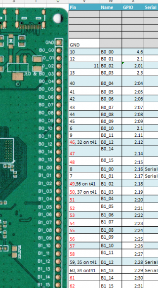
Thats exactly what I mean. Route a couple to the 1x40 header so a shield can get access. As for a todo list. As far as I know @KurtE gave it to you in post #1009: New T5 15/A1 AD_B1_03 USB_OTG1_OC QTIMER3_TIMER3 LPUART2_RX SPDIF_IN...
-
KurtE reacted to ThirdEarthDesign's post in the thread Tips on how to remove remembered devices from Windows, particularly handy when changing a Teensy device name in usb_desc.h with Like.
This is less of a question and more of a comment in case someone else finds it helpful.. But if like me you've modified the usb_desc.h file to change the name of a device or you've changed something in the usb.desc.c file, but Windows isn't...
-
KurtE reacted to ThirdEarthDesign's post in the thread Removing Unwanted Axis/Axes from a Joystick with Like.
Just a quick update on this, I managed to get it to work as I wanted. Removed 3x axes and the HAT switch. I amended usb_desc.h to reduce the Joystick size to 10 (I didn't quite need that many bytes, but it wouldn't compile with anything less...
-
KurtE replied to the thread BUILTIN_SDCARD not defined when switching from T3.5 to T4.1 compiles.It really helps to see the actual code: If that file is actually like: #include <SdFat.h> ... class SNFileRW { private: SdFat sdEx; ... } int SNFileRW::SN_SD_setup() { // returns 0 if successful, else error code #ifdef ARDUINO_TEENSY35...
-
KurtE reacted to mjs513's post in the thread BUILTIN_SDCARD not defined when switching from T3.5 to T4.1 compiles with Like.
With all that said you can actually mix and match SD and SDfat commands. Take a look at the SdFat_Usage example in the SD library. Note: SD is linked to the SDfat library that is installed with Teensyduino (either for 1.8.19 or 2.2.0 IDE's)...
-
KurtE reacted to jmarsh's post in the thread BUILTIN_SDCARD not defined when switching from T3.5 to T4.1 compiles with Like.
Try putting #define BUILTIN_SDCARD 254 before you #include SdFat.h. There is code inside that header that depends on it being defined, so if you put it after the file is included (like in your first post) it's not going to work. (The fact that...
-
KurtE replied to the thread Equivalent to Port Manipulation on Arduino.As mentioned, there are port. GPIO1-5 (they are also known as GPIO6-9), The pins on GPIO1 in normal mode are on GPIO6 in fast mode. The Teensy startup code sets all of the pins into fast mode. If you have not already done so, would recommend...
-
-
Thanks for checking :)
-
KurtE replied to the thread T4 Pixel Pipeline Library.Looks like it runs on my MMOD with ILI9488 :D
-
Quick update: Pushed latest changes to repo: https://github.com/mjs513/T4_PXP/tree/pxp_t4_mods fixed a minor bug when image_width > image_height. added some comments. theoretically you should just be able to drop the PXP functions into your...
-
Ok folks. While testing what I had with different size images than the flexio_teensy_mm found that there were several issues with rotation and scaling. So for the past few days been working on resolving those issues and finally found the...
-
KurtE replied to the thread New Camera Library for Teensy Micromod/4.1.Not sure, might be interesting to try... Although my goal here is to use the same wiring to support as many of the Arduino/Arducam/Adafruit/Waveshare cameras that have the same breakout pinout. If my main goal is to support the 4 bit HM01b0 on...
-
Couldn't you just connect each input pin twice (in the order 32103210) and pretend it's regular 8-bit?
-
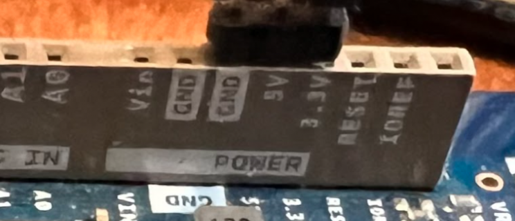
Oh just one more thing, Would be nice if you could maybe substitute a couple 5v pins for the 3.3v pins. Would make it easier when creating a shield.
-
KurtE replied to the thread New Camera Library for Teensy Micromod/4.1.Soon I will be out again doing more yard/garden work... But thought I would mention that I wanted to get all of the cameras to work on T4.1 on the CSI pins, that worked on the Micromod with FlexIO. The main problem child is the Arducam HM01b0...
-
-
The idea is to make the gen5 to have the pins needed, then from that I have already planned to make a shield for the two screens that @Rezo has in his possesion. Other shields can be done by you guys as well. And of course the Gerber files and...
-
KurtE replied to the thread using timers for signal generation?.You might look at @luni library: https://github.com/luni64/TeensyTimerTool/wiki For most of these things, I end up looking at the Reference Manual for the processor. There are links to this on the product pages. Potentially PWM might for your...
-
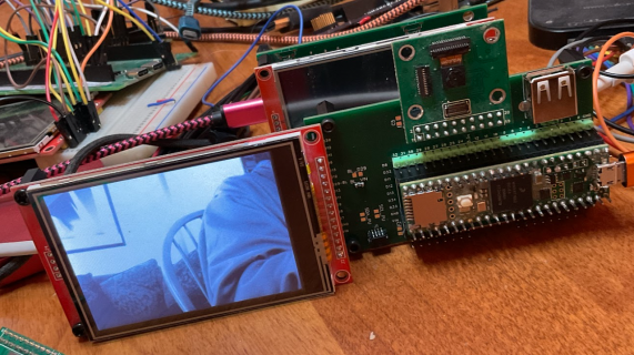
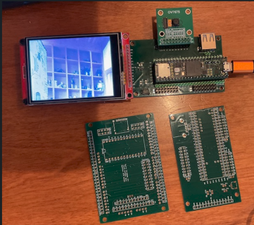
Would agree as long as the edge pin connectors are suitable to add a adapter on top it would be better. This is the adapter I made for the sdram board (note positions are off for the display and camera - have to move them fo the next iteration).
-
KurtE replied to the thread Call to arms | Teensy + SDRAM = true.I totally agree with @BriComp that it would be great. However, if that is not feasible or too many options. As long as the boards are reasonably laid out and preferably as I mentioned earlier, I would create a quick and dirty shield that does...
-
-
KurtE replied to the thread USBHost_t36 and FTDI device - so close!.You might try adding userial.flush(); after the writes To see i it helps
-
I would like to add my two-penneth. As I see it groups of pins have many particular functions. Might it not be a good idea to also route the pins to functional connectors. It is likely that some connectors will have an overlap of pins. That does...
-
KurtE replied to the thread New Camera Library for Teensy Micromod/4.1.Quick update, I am now actually capturing some of the JPG images using DMA :D More or less along the line I mentioned. A few wrong turns here and there but the MATCH shifter finds the match, and it's callback enables the main shifters Interrupt...
-
I agree from what I remember and posted before.
-
-
Loading…
-
Loading…