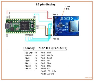
My friend and I both have a couple of teensey 3.1, and an assortment of the popular HY-1.8 SPI TFT displays. There are mainly 2 types of 1.8" display, the 16 pin and the 10 pin. For quite a while now, weve been trying to get these to work and neither of us has managed to get anything to show on the screens. Im very much a novice, but my friend is a seasoned hardware guy and he's given up after spending 2 days on this.
The first attempts were using the Adafruit files from here... https://www.adafruit.com/products/358 This is intended for the 10 pin display but doesnt seem to work.
Then trying to get a generic 16 pin again using adafruit libry files from here... https://github.com/adafruit/Adafruit-ST7735-Library
and here... https://github.com/adafruit/Adafrui...master/examples/graphicstest/graphicstest.ino
The script compiles and verifies ok, and we can upload without a problem, once the software is running, the orange LED will flash a few times for about 30 seconds then nothing. There isnt the slightest hint of anything on the screens.
I could understand if it was just me having problems, but my friend who has streets more experience then me also having problems, i dont understand. Does anyone have any clues or a link to a foolproof set up that definately works?
Any help would be immensely appreciated.
John


