Limits of delay effect in audio library

Excellent news, glad we got it sorted out. It’s prompted me to improve the documentation for the PR branch (it shows up in the Design Tool), so once it’s in, things should be a bit easier for everyone.
 
Hi everyone, I would like to extend RAM on the Teensy 4.1 to make a four channel looper.

I would like to make a new version of Frank's board for the APS6404L-3SQR-SN 8MB SPI memory chip with 8 chips on it.

I am currently using Paul's CS42448_T4_TEST2 board.
https://oshpark.com/shared_projects/gVFy0fWQ

Looking at Frank's memoryboard4,
https://oshpark.com/shared_projects/KZt5PaU7

it looks like these two boards can be stacked, with Frank's board using pin 7 for MOSI and pin 12 for MISO on the Teensy 4.1. I guess this is possible since I think someone earlier in this thread tried it. If so, it seems to me the new board should use the same SPI pins to minimize confusion.

To use eight memory chips, all eight outputs of the 74LCX138 need to be used. This brings up the question why Frank put the 74LCX126 on memoryboard4. Can/should it be removed to allow two more memory chips on a new board?

Thanks
Doug
 
While I have little experience with the audio capabilities of the T4.1, this thread does raise some interesting questions about memory management. The one that intrigues me the most is whether it would be possible to use a file on the SD card of the T4.1 to hold the audio data for later playback. With a bit of care with buffer management, it should be possible to pipe several channels of audio to the SD card for later retrieval as the echo output.

A key question is whether a single file can be open for writing by one process and open for reading at a different location by another process (Like a Linux pipe??). If that is not possible you would need to alternate between two files, one for reading and one for writing. At appropriate times, the files would switch (easier said than done, I suppose!)
 
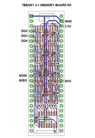
Hi everyone, here is the first draft of the Teensy 4.1 memory board with eight SPI memory chips.

The MOSI and MISO connections are different than Frank's Teensy 3.x version, which seems to me to be necessary for the 4.1

I removed the 74LCX126 buffer to obtain all eight output pins on the 74LCX138. I am not sure why the buffer is there.

I didn't add the pulldown resistors on the digital pins DO2, 3 and 4, but perhaps I should. Is there a memory corruption concern on power up? Perhaps pulldowns are just best practice here?

Teensy41Memory.png

Comments and critiques welcome. My aim is to piggy back this onto Paul's CS42448_T4_TEST2 board.
https://oshpark.com/shared_projects/gVFy0fWQ and record four channels of audio.

I am new here. Should this be a new thread?

Thanks,
Doug
 
Frank is still around, as mcu32 - maybe he’ll pipe up?

If I were you I’d try to track for fitting pull-downs (you don’t have to fit them), and maybe some links to change the device selection lines from D2 to D4 to other pins.

If you make enough boards I’d be interested to test one and add support to the library.
 
Okay thank you!

I added locations for the pulldowns.

Teensy41MemoryPullDowns.png

Can you please clarify "links to change the device selection lines." Is this just a naming thing, like I should use C0/C1/C2 instead of DO2/DO3/DO4? If so, I agree. Or are you talking about moving to different pins altogether?

Once this comes together, I will post on github and run a few copies with Osh Park.
I was thinking in terms of having the option to use different pins as chip select. D2-4 are also I2S2, so might well be wanted for an audio project. There aren’t many pins on a Teensy 4.0 that can’t be used for some audio function or another, but a 4.1 gives a few more options.

Please let me know when you’re ready to run and the likely cost of a board or two, plus shipping to the UK. I can populate them myself, bare PCB is fine.
 
Great, thanks. One point that’s just occurred to me … as it is there’s always one PSRAM enabled, so the SPI bus can’t be used for anything else. That wasn’t an issue with only 6 of them, of course, as there are a couple of unused addresses.
 
The 74LCX138 has three pins E1,E2,E3 to enable/disable it so that more memory can be added to the same SPI bus. I did not bring them out to the board pins though. It's easy to do in the next rev, but it would consume more digital I/O.
 
Great, thanks. One point that’s just occurred to me … as it is there’s always one PSRAM enabled, so the SPI bus can’t be used for anything else. That wasn’t an issue with only 6 of them, of course, as there are a couple of unused addresses.

It turns out that all the CS lines must be able to go high because leaving one low by default corrupts the memory on that chip. I have broken out pin 4 on the 74LCX138 to Teensy 4.1 pin 5. Setting this HIGH sends all the CS lines high.

It appears I am able to run this board successfully at 60MHz SPI clock, although maybe I am jumping to desired conclusions.

Project has been updated to R1 on github and OSH Park.
https://github.com/studiohsoftware/Teensy41Memory
 
Curious, you’d think that so long as there’s no other code using the SPI bus it’d be OK (if slightly grubby) to leave a CS low.

I think Paul S would mutter about stability over temperature and voltage extremes, but if 60MHz works for you, go for it!
 
I’ve just finished a test of a very long audio delay program that uses the T4.1 SD Card as buffer memory for a 105MB circular buffer. With 44.1KHz stereo input, this buffer allows delays up to about 10 minutes. It does require a bit of a hardware investment: a 128MB SanDisk ultra micro SD card which costs about $16.

To test the delay software, I collected stereo input from the SGTL5000 line in input from music playing through the headphone output of an iPad. When I monitored the output with a pair of Sony headphones, the Beethoven symphony came through loud and clear. However, I may have missed a few glitches, as I was reading through the source code for the delay functions in the audio library. I let the music play and monitored it for about two hours. This is important, as the SD-card file serving as the extended buffer of 105.7MB (good for delays up to 10 minutes) was cycled through several times. After the first cycle through the buffer, the zeroed blocks from the initialization have been overwritten one or more times. This caused the maximum block write time to rise from about 20mSec to about 37 mSec. as the reused blocks had to be erased or swapped for other blocks. (The primary (pre-SD card) RAM buffers are good for about 80mSec of buffering during SD Writes.)

I’ve attached the code for the demo (211 lines) and the semi-generic CircrBuff_SD (~380 lines) as a zip file. the CircBuff_SD class can be easily adapted to other applications (such as transient loggers). My tests were run with the T4.1 CPU clock at 150MHz, so I think there are plenty of CPU cycles left for more complex operations if you boost the clock rate.

At this point, this software is a solution looking for a problem. Here are the questions I have:

1. What are the usage scenarios for very long audio delays?

2. What other applications might benefit from 10 to 100 minutes of circular buffer storage? I’ll be asking some friends in the oceanographic data collection business the same question. Perhaps they have a problem looking for a solution. I think they may have lots of problems looking for solutions—umm, let me rephrase that: “They may have lots of research opportunities looking for solutions.”

2. Is this software worth the effort to convert to an audio-specialized library? I’ve looked over the source code for audioDelay_extmem, and it doesn’t seem that I would have to spend too much time building a shell around the generic Circ_buff_SD class to become compatible with the audio library conventions.


View attachment Del10Minute_linein_CBSD.zip
 
why Frank put the 74LCX126 on memoryboard4. Can/should it be removed to allow two more memory chips on a new board?

The 74LCX126 is for level shifting, because Teensy3 is 5V, the memory chips are not. It's not needed for Teensy4.

I am building a memory expansion board that's shorter so it fits on Teensy 4.0 footprint (also 4.1 of course) and has (6) 23LC1024 chips. It uses the same memory addressing scheme as the original Teensy 3 Memoryboard so hopefully it'll be recognized by the libraries.
I did wonder about that part…

I have a PR that nearly got merged (https://github.com/PaulStoffregen/Audio/pull/433), before Paul got distracted, which allows use of a PSRAM instead of a single 23LC1024, giving 95s delay. Easier than a custom board, unless you have a compelling reason to build one anyway!
 
@dougcl's 64MB memory board is now supported by my PR for improvements to AudioEffectDelayExternal, and I've also fixed a rather nasty instance of the "static initialization order fiasco" which results in any attempt to use the AudioEffectDelayExternal ending in a crashed Teensy. I (think I) rewound to the current issue of Teensyduino and it was still borked, so it's possibly due to changes in the gcc toolchain.
 
Just pushed up a minor improvement, so if you want to partially populate dougcl's PCB, you can (I believe) do it in numerical order, e.g. just fit IC1 through IC5 for 40MB (nearly 8 minutes) of delay memory. Only tested with IC1 and IC2 fitted, as that's all the PSRAM I have to hand right now. Further testing and bug reports welcome! Here's my test code:
Code:
#include "Arduino.h"

#include <Audio.h>
#include <Wire.h>
#include <SPI.h>
#include <SD.h>
#include <SerialFlash.h>

#define DUMMY_TIME_MS 92700.0f
// GUItool: begin automatically generated code
AudioSynthWaveformModulated waveformMod;   //xy=183,174
// One PSRAM 8MB chip is 95108.93ms of delay
// With a SPI bus of 31.41MHz, and 3 delay objects with 3, 3, and 1 tap, we
// need to do 3 writes and 7 reads of 128*2*8 = 2048 bits, so 20480 bits,
// which will take about 0.68ms. This happes every 2.9ms, so expect
// a CPU load of 22.4%. We get about 19%, so fairly close.
AudioEffectDelayExternal delayExt(AUDIO_MEMORY_PSRAM64_X8,   1400.0f);      //xy=322,396
AudioEffectDelayExternal dummyDelay(AUDIO_MEMORY_PSRAM64_X8,DUMMY_TIME_MS);     // make next delay cross chip boundary
AudioEffectDelayExternal delayExt1(AUDIO_MEMORY_PSRAM64_X8,2000.0f); //xy=329,641
AudioMixer4              mixer4;       //xy=604,213
AudioMixer4              mixer5; //xy=611,458
AudioOutputI2S           i2s;           //xy=811,148
AudioConnection          patchCord1(waveformMod, 0, mixer4, 0);
AudioConnection          patchCord2(delayExt, 0, mixer4, 1);
AudioConnection          patchCord3(delayExt, 1, mixer4, 2);
AudioConnection          patchCord4(delayExt, 1, mixer5, 0);
AudioConnection          patchCord5(delayExt, 2, mixer4, 3);
AudioConnection          patchCord6(delayExt1, 0, mixer5, 1);
AudioConnection          patchCord7(delayExt1, 1, mixer5, 2);
AudioConnection          patchCord8(delayExt1, 2, mixer5, 3);
AudioConnection          patchCord9(mixer4, delayExt);
AudioConnection          patchCord10(mixer4, 0, i2s, 1);
AudioConnection          patchCord11(mixer5, delayExt1);
AudioConnection          patchCord12(mixer5, 0, i2s, 0);
AudioControlSGTL5000     sgtl5000_1;     //xy=811,195
// GUItool: end automatically generated code


void setup() {
  Serial.begin(115200);

  Serial.println("Starting audio...");
  AudioMemory(40);

  mixer4.gain(0,0.71f);
  mixer4.gain(1,0.05f);
  mixer4.gain(2,0.20f);
  mixer4.gain(3,0.71f);

  Serial.println("Set up delayExt object");
  delayExt.delay(0,23.0);
  delayExt.delay(1,137.0);
  delayExt.delay(2,911.0);
  
  mixer5.gain(0,0.71f);
  mixer5.gain(1,0.05f);
  mixer5.gain(2,0.20f);
  mixer5.gain(3,0.71f);

  Serial.println("Set up delayExt1 object");
  delayExt1.delay(0,29.0);
  delayExt1.delay(1,241.0);
  delayExt1.delay(2,1297.0);
  
  Serial.println("Set up dummyDelay object");
  uint32_t now = micros();
  dummyDelay.delay(0,29.0);
  now = micros() - now;
  float SPIrate = DUMMY_TIME_MS / 1000.0f * AUDIO_SAMPLE_RATE * 2 * 8 / now;
  Serial.printf("SPI bus speed = %.2fMHz\n",SPIrate);

  Serial.printf("Maximum delay is %.3fms\n",delayExt.getMaxDelay());
  int x = sizeof(((audio_block_t*) 0)->data[0]);
  Serial.printf("Sample size is %d bytes\n",x);

  sgtl5000_1.enable();
  sgtl5000_1.volume(0.2);
  sgtl5000_1.lineOutLevel(14); // 2.98V pk-pk
}


uint32_t next;
void loop() {
  if (millis() > next)
  {
    next += 5000;    
    waveformMod.begin(1.0f,220.0f,WAVEFORM_SINE);
    delay(10);
    Serial.printf("Usage %.2f, max %.2f\n",AudioProcessorUsage(),AudioProcessorUsageMax());
    AudioProcessorUsageMaxReset();
    waveformMod.amplitude(0.0f);
    
  }
}
Note that the fix for the static initialization order fiasco means that zeroing a delay object's memory is deferred until the first call to delay(), hence there's about a 2s wait when dummyDelay.delay(0,29.0); is executed. The dummyDelay object is only used to ensure that delayExt1 memory spans the end of one chip and the start of the next. Expect a 16s wait at some point if you have all chips fully in use!
 
im just poking around here with one of doug cl boards, does this test make sense?
#include <SPI.h>
#include <Arduino.h>

#define SPISETTING_PS SPISettings(31'000'000, MSBFIRST, SPI_MODE0) // Adjusted speed for PSRAM
#define MEMBRD8M_CS0_PIN 2
#define MEMBRD8M_CS1_PIN 3
#define MEMBRD8M_CS2_PIN 4
#define MEMBRD8M_ENL_PIN 5 // Enable pin, active low
const unsigned long MAX_ADDRESS = 0x3FFFFF; // Maximum address for 64MB chips in 16-bit mode
void setup() {
Serial.begin(9600);
SPI.begin();
pinMode(MEMBRD8M_CS0_PIN, OUTPUT);
pinMode(MEMBRD8M_CS1_PIN, OUTPUT);
pinMode(MEMBRD8M_CS2_PIN, OUTPUT);
pinMode(MEMBRD8M_ENL_PIN, OUTPUT);
initPSRAM();
unsigned long startTime = micros();
// Sequentially write to and read from each chip
for (int chip = 0; chip < 8; chip++) {
for (unsigned long addr = 0; addr <= MAX_ADDRESS; addr += 1024) {
writePSRAM(chip, addr, 0xA5A5);
uint16_t data = readPSRAM(chip, addr);
}
}
unsigned long endTime = micros();
// Output result
Serial.print("Total operation time (microseconds): ");
Serial.println(endTime - startTime);
}
void loop() {

}
void setMuxPSRAMx8(int chip) {
digitalWrite(MEMBRD8M_CS0_PIN, ~chip & 2);
digitalWrite(MEMBRD8M_CS1_PIN, ~chip & 4);
digitalWrite(MEMBRD8M_CS2_PIN, chip & 1);
digitalWrite(MEMBRD8M_ENL_PIN, LOW);
}
void initPSRAM() {
SPI.beginTransaction(SPISETTING_PS);
for (int i = 0; i < 8; i++) {
setMuxPSRAMx8(i);

}
setMuxPSRAMx8(-1);
SPI.endTransaction();
}
void writePSRAM(int chip, uint32_t address, uint16_t data) {
SPI.beginTransaction(SPISETTING_PS);
setMuxPSRAMx8(chip);
SPI.transfer(0x02); // Command for write
SPI.transfer((address >> 16) & 0xFF); // High byte
SPI.transfer((address >> 8) & 0xFF); // Middle byte
SPI.transfer(address & 0xFF); // Low byte
SPI.transfer16(data); // Data to write
setMuxPSRAMx8(-1); // Deselect the chip
SPI.endTransaction();
}
uint16_t readPSRAM(int chip, uint32_t address) {
uint16_t data;
SPI.beginTransaction(SPISETTING_PS);
setMuxPSRAMx8(chip);
SPI.transfer(0x03); // Command for read
SPI.transfer((address >> 16) & 0xFF); // High byte
SPI.transfer((address >> 8) & 0xFF); // Middle byte
SPI.transfer(address & 0xFF); // Low byte
data = SPI.transfer16(0xFFFF); // Dummy data to read
setMuxPSRAMx8(-1); // Deselect the chip
SPI.endTransaction();
return data;
}
 
I never said that! I think you meant to use the </> code tag, which would make things more readable, too... Though bits do resemble my updated delay code - you missed a bit when you copied setMuxPSRAMx8(), so selecting chip -1 doesn't disable the mux by setting MEMBRD8M_ENL_PIN HIGH.

Doesn't make much sense as-is. All you seem to be doing is displaying the time taken to write 1k uint16_t values to each of 8 possible PSRAM chips, and then read them back. You haven't checked to see if the read-back value matches what was written.
ah apologies!, i was on the go....ill deep dive into this
 
Could someone tell me roughly how long a delay is possible with the delay effect in the audio library? I'm building a hardware delay line for music synthesis and wondering whether the Teensy 3.1 is appropriate for longer delays (2000ms). I realize that other code will also consume memory. For this application, the only extra code would be instructions necessary for reading controls for real-time parameter changes.

Thanks very much for your help,
Michael
In this post from 2023 I demonstrated that very long delays are possible using a buffer on SD card on a T4.1.


I haven’t followed up on this capability as I’ve been occupied with other projects.
 
im fairly interested in how to use extmem in depth for uses outside delay, like lots of loop buffers. i was just looking over the extmem.h and extmem.cpp files in h4yn0nnym0u5e github to get an idea on how to use them
 
OK ... the AudioExtMem class isn't exactly well-documented ... sorry. The idea is that it's used as a base class for any derived (probably but not necessarily audio) class to abstract the interface to large buffer memories, either SPI-based or memory mapped. At instantiation you define the memory type as one of the options in AudioEffectDelayMemoryType_t, along with the desired size, then just use the (protected) read and write member functions to access the memory, without having to write yet another copy of the code that can do it. For loops and delays, the wrap versions of the access functions are to my mind particularly snazzy!

Obviously SD cards are the way to go for humongous buffers, and will also be faster than SPI-based RAM if you use the built-in socket on a Teensy 4.1. Card wear could be a long-term issue, but probably not worth worrying about as it's so easy to pop in a known-fresh card if you have a gig you can't afford to lose.
thats good to know, im going to pick it apart and pull something together, it looks good
 
Let me know if there’s any improvement you think belongs in there, so long as it’s strictly relevant to the allocation of and access to memory. That probably doesn’t include resampling, I’d like to keep it pretty simple at this low level…
 
Back
Top