Code:
Board: Teensy 3.2
Software Details: MacOS Sierra (10.12), Arduino 1.6.7, Teensyduino 1.27
Components: Photodiode (375 x 10^3 Ohm); Variable Resistor (3 x 10^9 Ohm). The Variable Resistor is a custom in house device. It contains a conductive material in the center (which is covered in a elastic rubber material) and their are two conductive strips (like the 2 metal wires that come off the sides of a normal resistor) that project off the two ends. Since the conductive material is flexible and the coating is also elastic, this allows me to apply pressure, stretch, etc. to the component, therefore changing its resistance.
Problem:
Hello,
I am trying to read the voltage change across a variable resistor, and based on that voltage change, turn the onboard Teensy LED ON/OFF.
First, I used a photodiode with a resistance of 375 kOhm to test my code. I attached the circuit as shown:
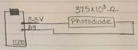
The LED turns on/off successfully upon shining a flashlight onto the photodiode.
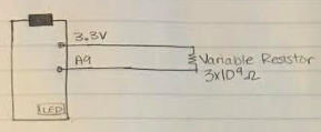
Second, I tried replacing the photodiode with a variable resistor with a base resistance of 3 x 10^9 Ohm (yes, that high, that's not a typo ). By base resistance, I mean it is a "resistor like" device that changes resistance according to the amount of pressure/strain applied to the device. It looks just a like a resistor, meaning it has two terminals that I can attach alligator clips to. However, when I attach the circuit and observe the serial monitor, it does not change values when pressure/strain is applied. The numbers just fluctuate between 800 and 900 randomly. The circuit was set up like this:
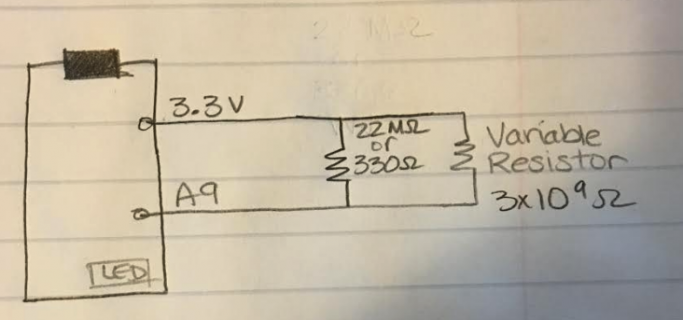
Third, I tried attaching a 330 Ohm resistor in parallel with the Variable Resistor, because maybe the incredibly high resistance of the Variable Resistor wasn't allowing enough current flow. This, also did not show any changes in the Serial Monitor when pressure/strain was applied. The numbers just fluctuate between 800 and 900 randomly. Then, I removed the 330 Ohm resistor and I tried attaching a 22 MOhm resistor in parallel with the Variable Resistor. I did this just to try without any logic, but the serial monitor again did not show any changes when pressure/strain was applied. The circuit set up was like this:
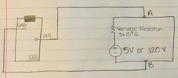
Finally, I tried attaching the Variable Resistor to its own power supply in order to pass either 5V or 120V through the Variable Resistor in order to increase current flow and consistency. Again, the Serial Monitor displayed no changes. This time the numbers just peaked at 1023 (both with 5V and 120V being applied across the resistor). The circuit set up was like this:
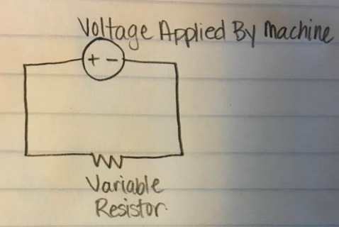
Also, I should note that when I use a machine we have in our lab to apply a voltage across the Variable Resistor, the machine reads and graphs the Current (y-axis) vs Time (seconds). And the machine does read and show that the current does change as pressure/strain is applied, but the Arduino serial monitor still shows no change even though the machine is showing change. The base resistance on the Variable Resistor was also calculated using this machine and the Variable Resistance also changes when a pressure/strain is applied. The circuit of the Variable Resistance attached to the machine is as follows:
I have no idea how the machine operates or anything about the company. It is a huge device (almost 4 ft. by 4 ft. big), which is connected to a computer program (I think LabView). I think the machine is irrelevant to my issue, but added the information just in case.
Question So, in case my question got lost in all the details: I am trying to read the voltage change across the variable resistor using the Teensy 3.2, but the Serial Monitor displays no meaningful change when pressure/strain is applied to the Variable Resistor.
I appreciate any constructive response to this post. It is a bit urgent, as I need to finish this by Friday.
UPDATE 10/25/16: So I found out that I am connecting my circuits some what incorrectly. Apparently connecting the variable resistor/photodiode as shown here is better. This does give me more stable readings off of the photodiode, but I still cannot get values to change with the variable resistor.
I have also tried using a 2N3904 NPN Transistor in an attempt to amplify the current, but I do not think I am doing that properly either because it is not giving me any changes in values, and in certain configurations it "disconnects" my Port so that the Serial Monitor no longer shows anything. Next I'm going to try an op-amp (LM741), but I really don't know how to begin with it.
Code:
//constants
const int analogPin = A9;    // pin that the sensor is attached to
const int ledPin = 13;       // pin that the LED is attached to
const int Threshold = 920;   //.2 milliamps


void setup() {
  // initialize the LED pin as an output:
  pinMode(ledPin, OUTPUT);
  pinMode(analogPin, INPUT);
  // initialize serial communications:
  Serial.begin(9600);
}

void loop() {
  // read the value of the potentiometer:
  int analogValue = analogRead(analogPin);
Serial.println(analogValue);
  // if the analog value is high enough, turn on the LED:
  if (analogValue < Threshold)
  {
    digitalWrite(ledPin, LOW);
    delay(1);
}
  else {
    digitalWrite(ledPin, HIGH);
  }

  // print the analog value:
  Serial.println(analogValue);
  delay(500);        // delay in between reads for stability
}Board: Teensy 3.2
Software Details: MacOS Sierra (10.12), Arduino 1.6.7, Teensyduino 1.27
Components: Photodiode (375 x 10^3 Ohm); Variable Resistor (3 x 10^9 Ohm). The Variable Resistor is a custom in house device. It contains a conductive material in the center (which is covered in a elastic rubber material) and their are two conductive strips (like the 2 metal wires that come off the sides of a normal resistor) that project off the two ends. Since the conductive material is flexible and the coating is also elastic, this allows me to apply pressure, stretch, etc. to the component, therefore changing its resistance.
Problem:
Hello,
I am trying to read the voltage change across a variable resistor, and based on that voltage change, turn the onboard Teensy LED ON/OFF.
First, I used a photodiode with a resistance of 375 kOhm to test my code. I attached the circuit as shown:

The LED turns on/off successfully upon shining a flashlight onto the photodiode.
Second, I tried replacing the photodiode with a variable resistor with a base resistance of 3 x 10^9 Ohm (yes, that high, that's not a typo

Third, I tried attaching a 330 Ohm resistor in parallel with the Variable Resistor, because maybe the incredibly high resistance of the Variable Resistor wasn't allowing enough current flow. This, also did not show any changes in the Serial Monitor when pressure/strain was applied. The numbers just fluctuate between 800 and 900 randomly. Then, I removed the 330 Ohm resistor and I tried attaching a 22 MOhm resistor in parallel with the Variable Resistor. I did this just to try without any logic, but the serial monitor again did not show any changes when pressure/strain was applied. The circuit set up was like this:

Finally, I tried attaching the Variable Resistor to its own power supply in order to pass either 5V or 120V through the Variable Resistor in order to increase current flow and consistency. Again, the Serial Monitor displayed no changes. This time the numbers just peaked at 1023 (both with 5V and 120V being applied across the resistor). The circuit set up was like this:

Also, I should note that when I use a machine we have in our lab to apply a voltage across the Variable Resistor, the machine reads and graphs the Current (y-axis) vs Time (seconds). And the machine does read and show that the current does change as pressure/strain is applied, but the Arduino serial monitor still shows no change even though the machine is showing change. The base resistance on the Variable Resistor was also calculated using this machine and the Variable Resistance also changes when a pressure/strain is applied. The circuit of the Variable Resistance attached to the machine is as follows:

I have no idea how the machine operates or anything about the company. It is a huge device (almost 4 ft. by 4 ft. big), which is connected to a computer program (I think LabView). I think the machine is irrelevant to my issue, but added the information just in case.
Question So, in case my question got lost in all the details: I am trying to read the voltage change across the variable resistor using the Teensy 3.2, but the Serial Monitor displays no meaningful change when pressure/strain is applied to the Variable Resistor.
I appreciate any constructive response to this post. It is a bit urgent, as I need to finish this by Friday.
UPDATE 10/25/16: So I found out that I am connecting my circuits some what incorrectly. Apparently connecting the variable resistor/photodiode as shown here is better. This does give me more stable readings off of the photodiode, but I still cannot get values to change with the variable resistor.
I have also tried using a 2N3904 NPN Transistor in an attempt to amplify the current, but I do not think I am doing that properly either because it is not giving me any changes in values, and in certain configurations it "disconnects" my Port so that the Serial Monitor no longer shows anything. Next I'm going to try an op-amp (LM741), but I really don't know how to begin with it.
Last edited:

