I am re-developing an environment-monitoring system that I first implemented with Arduinos. The system comprises a half-dozen or so peripheral stations, a base station, and a Windows application.
Each peripheral station is built around a Teensy 3.5. Various peripheral stations have various connected sensors around my house (current transformers; sensors of pressure, light, temperature, water depth, etc.; a rain gauge; and an anemometer/wind vane). The peripheral stations communicate with the base station using XBee transceivers. All the peripheral stations run the same code, and DIP switches on the peripheral-station board tell the station what sensors & display units it has.
The base station (also built around a Teensy 3.5) runs continuously, 24-7. It is connected to a PC running Windows through its USB port, but the Windows application runs only intermittently. The base station timestamps data reports from the peripheral stations, and then either (a) stores the data on its SD card, or, if the Windows application is running, (b) dumps stored data and newly-received data to the Windows application.
The problem I'm having is with the anemometer. The anemometer is conventionally constructed, with a rotor that spins as driven by the wind. The anemometer is connected to its peripheral station by two wires to form a normally-open circuit that is closed briefly once per revolution. A closure rate of 1 Hz corresponds to a wind speed of 1.492 MPH.
At the peripheral station, one of the two wires from the anemometer is grounded, and the other is (a) pulled up to 3V3 through a 10K resistor, and (b) connected to digital pin 24. An ISR attached to that pin, triggered by a falling level, counts revolutions, and conventional code does the rest.
The problem I'm having is that the system worked as designed for half a day or so, but then the anemometer events stopped being recorded. The hardware & software were not deliberately changed in any way, so I have some fear that an electrical problem has fried the Teensy's D24. Again, substantially identical code was used with Arduinos with no problems; that is why I think I may have inadvertently exceeded the dynamic tolerance of the Teensy.
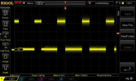
The signal coming in to the pin looks like this
 .
.
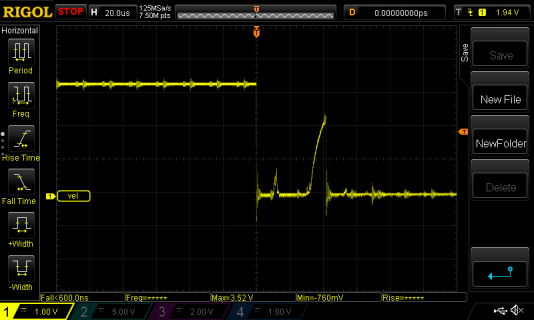
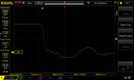
The oscilloscope measures its range as [-720 mV, +4.16V], but my multimeter calls it [0, 3.1V]. At higher time-resolution, a serious switch-bounce is visible
 .
.
(I can see this with or without the Teensy attached) Double interrupts may have occurred, but the code (before interrupts stopped arriving on D24) avoided double counting.
The fall time of the signal is too short for accurate measurement with my equipment.

The code for the whole system is about 350 KB; I will upload all of it if anyone is willing to go through it. As a focused start, here is the top-level code of a peripheral station
and here is the code that supports the anemometer & wind vane.
Each peripheral station is built around a Teensy 3.5. Various peripheral stations have various connected sensors around my house (current transformers; sensors of pressure, light, temperature, water depth, etc.; a rain gauge; and an anemometer/wind vane). The peripheral stations communicate with the base station using XBee transceivers. All the peripheral stations run the same code, and DIP switches on the peripheral-station board tell the station what sensors & display units it has.
The base station (also built around a Teensy 3.5) runs continuously, 24-7. It is connected to a PC running Windows through its USB port, but the Windows application runs only intermittently. The base station timestamps data reports from the peripheral stations, and then either (a) stores the data on its SD card, or, if the Windows application is running, (b) dumps stored data and newly-received data to the Windows application.
The problem I'm having is with the anemometer. The anemometer is conventionally constructed, with a rotor that spins as driven by the wind. The anemometer is connected to its peripheral station by two wires to form a normally-open circuit that is closed briefly once per revolution. A closure rate of 1 Hz corresponds to a wind speed of 1.492 MPH.
At the peripheral station, one of the two wires from the anemometer is grounded, and the other is (a) pulled up to 3V3 through a 10K resistor, and (b) connected to digital pin 24. An ISR attached to that pin, triggered by a falling level, counts revolutions, and conventional code does the rest.
The problem I'm having is that the system worked as designed for half a day or so, but then the anemometer events stopped being recorded. The hardware & software were not deliberately changed in any way, so I have some fear that an electrical problem has fried the Teensy's D24. Again, substantially identical code was used with Arduinos with no problems; that is why I think I may have inadvertently exceeded the dynamic tolerance of the Teensy.
The signal coming in to the pin looks like this
 .
. The oscilloscope measures its range as [-720 mV, +4.16V], but my multimeter calls it [0, 3.1V]. At higher time-resolution, a serious switch-bounce is visible
 .
. (I can see this with or without the Teensy attached) Double interrupts may have occurred, but the code (before interrupts stopped arriving on D24) avoided double counting.
The fall time of the signal is too short for accurate measurement with my equipment.

The code for the whole system is about 350 KB; I will upload all of it if anyone is willing to go through it. As a focused start, here is the top-level code of a peripheral station
Code:
// peripheral
// routines here have IDs 10xxx
#include "H:\application-specific\generic C compiler\DateFile.c"
// defines WhenCompiled

#include "G:\source code\Teensy\Teensy 3.5 pins.h"
// ************ pin assignments ************************
#define WindowsSerial Serial
#define XBeeSerial Serial1
// XBee uses                      pin00Serial1RX_MOSI1
// XBee uses                      pin01Serial1TX_MISO1
const int pinDHT22Data          = pin02Generic;
// BMP085 uses                    pin03SCL2
// BMP085 uses                    pin04SDA2;
const int pinTVDC               = pin05TV;
const int pinClearScreenInt     = pin06Generic;
#define OLEDSerial Serial3
// OLED uses                      pin07RX3
// OLED uses                      pin08TX3
const int pinRainGaugeInt       = pin09RX2CS0;
const int pinTVCS               = pin10TX2CS0TV;
const int pinTVData             = pin11MOSI0TV;
const int pinTVReset            = pin12MISO0;
const int pinTVSCLK             = pin13SCK0TV;
const int pinBlink              = pin13SCK0TV;
const int pinGND_HasTeensyView  = pin14A00;
const int pinGND_HasOLED        = pin15A01CS0TV;
const int pinGND_HasPhotocell   = pin16A02;
const int pinGND_HasDHT22       = pin17A03;
const int pinGND_HasCTs         = pin18A04;
const int pinGND_HasDepth       = pin19A05;
const int pinGND_HasBMP085      = pin20A06CS0;
const int pinGND_HasACDetect    = pin21A07CS0;
const int pinGND_HasRainGauge   = pin22A08;
const int pinGND_HasWindGauge   = pin23A09;
const int pinAnemometerInt      = pin24Generic;
const int pinDepthA             = pin25Generic;
const int pinDepthB             = pin26Generic;
const int pinACPowerLeft        = pin31A12RX4CS1;
const int pinACPowerRight       = pin32A13TX4SCK1;
const int pinDepth              = pin33A14TX5;
const int pinPhotocell          = pin34A15RX5;
const int pinGND_Option1        = pin35A16;
const int pinGND_Option2        = pin36A17;
const int pinGND_ShowBigTemp    = pin37A18SCL1;
const int pinGND_LargeOLED      = pin38A19SDA1;
const int pinWindDirection      = pin39A20;
#define   pinGND_InIDE                 A21
#define   pinGND_Speedup               A22
#define   pinAC_G                      A25
#define   pinAC_F                      A26

// unused
//   D27-D30        LL
//   A10, A11       inside UR

// ************ end pin assignments ************************
bool InIDE;
// routines 110xx
#include "G:\source code\Teensy\shared\Display.inc"

// routines 115xx
#include "G:\source code\Teensy\shared\TeensyView.inc"
tTeensyView TV;

// routines 112xx
#include "G:\source code\Teensy\shared\OLED.inc"
tOLED OLED;

// routines 118xx
#include "G:\source code\Teensy\Home Control 2\Peripheral3\include files\ClearScreen.inc"

// routines 12xxx
#include "G:\source code\Teensy\Home Control 2\Peripheral3\include files\infrastructure.inc"

// routines 13xxx
#include "G:\source code\Teensy\Home Control 2\Peripheral3\include files\line buffer.inc"

// routines 14xxx
#include "G:\source code\Teensy\Home Control 2\Peripheral3\include files\XBee.inc"
tXBee XBee;

// routines 15xxx
#include "G:\source code\Teensy\Home Control 2\shared\Reporter.inc"
tReporter Reporter;

// routines 16xxx
#include "G:\source code\Teensy\Home Control 2\Peripheral3\include files\ACDetector.inc"
tACDetector ACDetector;

// routines 17xxx
#include <i2c_t3.h>
#include "G:\source code\Teensy\Home Control 2\Peripheral3\include files\BMP085.inc"
Adafruit_BMP085_Unified BMP085;

// routines 18xxx
#include "G:\source code\Teensy\Home Control 2\Peripheral3\include files\CurrentTransformers.inc"
tCurrentTransformers CurrentTransformers;

// routines 19xxx
#include "G:\source code\Teensy\Home Control 2\Peripheral3\include files\Depth.inc"
tDepth Depth;

// routines 20xxx
const bool InThermostat = false;
#include "DHT.h"
DHT TheDHT(pinDHT22Data, DHT22);  // must precede DHTRRF inclusion
#include "G:\source code\Teensy\Home Control 2\shared\DHTRRF.inc"
tDHTRRF DHTRRF;

// routines 21xxx
#include "G:\source code\Teensy\Home Control 2\Peripheral3\include files\Photocell.inc"
tPhotocell Photocell;

// routines 22xxx
#include "G:\source code\Teensy\Home Control 2\Peripheral3\include files\rain gauge.inc"

// routines 23xxx
#include "G:\source code\Teensy\Home Control 2\Peripheral3\include files\anemometer.inc"
tWindGauge WindGauge;


void setup()
  { // routine ID 10000
    pinMode(pinBlink, OUTPUT);
    Serial.begin(9600);
    InIDE                  = IsGrounded(pinGND_InIDE,         "in IDE"    );
    if (InIDE)
      { while (not Serial); }

    HasACDetect            = IsGrounded(pinGND_HasACDetect,   "ACDetect"    );
    HasBMP085              = IsGrounded(pinGND_HasBMP085,     "BMP085"      );
    HasCurrentTransformers = IsGrounded(pinGND_HasCTs,        "HasCTs"      );
    HasDepth               = IsGrounded(pinGND_HasDepth,      "depth"       );
    HasDHT22               = IsGrounded(pinGND_HasDHT22,      "DHT22"       );
    HasOLED                = IsGrounded(pinGND_HasOLED,       "OLED"        );
    HasPhotocell           = IsGrounded(pinGND_HasPhotocell , "photocell"   );
    HasRainGauge           = IsGrounded(pinGND_HasRainGauge,  "rain"        );
    HasTeensyView          = IsGrounded(pinGND_HasTeensyView, "TeensyView"  );
    HasWindGauge           = IsGrounded(pinGND_HasWindGauge,  "wind"        );
    LargeOLED              = IsGrounded(pinGND_LargeOLED,     "large OLED"  );
    ShowBigTemp            = IsGrounded(pinGND_ShowBigTemp,   "show big TRH");

    if (not InIDE)
      { Serial.print("not "); }
    Serial.println("in IDE");

    //    Blink(2);

    if (HasTeensyView)                                       // TeensyView
      { char Message1[] = "About to start TeensyView";       // ..
        TellWindows(Message1, 10001);                        // ..
        TV.setup();                                          // ..
        Serial.println("back from TV");
      }                                                      // ..

    if (HasOLED)                                             // OLED
      { char Message2[] = "About to start OLED";             // ..
        TellWindows(Message2, 10002);                        // ..
        if (LargeOLED)                                       // ..
          { OLED.setupLarge(); }                             // ..
        else                                                 // ..
          { OLED.setup(); }                                  // ..
      }                                                      // ..
    SetupClearScreen();

    if (InIDE)                                               // XBee
      { char Message3[] = "XBee not used";                   // ..
        TellWindows(Message3, 10003); }                      // ..
    else                                                     // ..
      { char Message4[] = "About to start XBee";             // ..
        TellWindows(Message4, 10004);                        // ..
        if (not XBee.Begin())                                // ..
           { Hang("XBee inoperative"); }                     // ..
      }                                                      // ..

    if (HasACDetect)                                         // AC detector
      { char Message5[] = "Starting AC detector";            // ..
        TellWindows(Message5, 10005);                        // ..
        ACDetector.setup();                                  // ..
      }                                                      // ..

    Reporter.setup();                                        // reporter

    if (HasBMP085)                                           // BMP085
      { char Message6[] = "Starting BMP085";                 // ..
        TellWindows(Message6, 10006);                        // ..
        BMP085.setup();                                      // ..
      }                                                      // ..

    if (HasCurrentTransformers)                              // current transformers
      { char Message7[] = "Starting current transformers";   // ..
        TellWindows(Message7, 10007);                        // ..
        CurrentTransformers.setup();                         // ..
      }                                                      // ..

    if (HasDepth)                                            // depth gauge
      { char Message8[] = "Starting depth gauge";            // ..
        TellWindows(Message8, 10008);                        // ..
        Depth.setup();                                       // ..
      }                                                      // ..

    if (HasDHT22)                                            // DHT22
      { char Message9[] = "Starting DHT22";                  // ..
        TellWindows(Message9, 10009);                        // ..
        DHTRRF.setup();                                      // ..
      }                                                      // ..

    if (HasPhotocell)                                        // photocell
      { char Message10[] = "Starting photocell";             // ..
        TellWindows(Message10, 10010);                       // ..
        Photocell.setup();                                   // ..
      }                                                      // ..

   if (HasRainGauge)                                         // rain gauge
      { char Message11[] = "Starting rain gauge";            // ..
        TellWindows(Message11, 10011);                       // ..
        SetUpRainGauge();                                    // ..
      }                                                      // ..

    if (HasWindGauge)                                        // anemometer
      { char Message12[] = "Starting wind gauge";            // ..
        TellWindows(Message12, 10012);                       // ..
        WindGauge.setup();                                   // ..
      }                                                      // ..

    char Message13[] = "setup complete";                     // done
    TellWindows(Message13, 10099);                           // ..
  } // setup

elapsedMillis msSinceLastDot;
unsigned int DotInterval = 30 * msOneSecond;

void loop()
  { // routine ID 10100
    Speedup = IsGrounded(pinGND_Speedup);

    if (msSinceLastDot > DotInterval)
      { if (TV.Available)
          { TV.PrintConstLine("."); }
         msSinceLastDot = 0;
      } // temporize

    ClearScreenCheck();

    if (HasACDetect)
      { ACDetector.loop(); }

    if (HasBMP085)
      { BMP085.loop(); }

    if (HasCurrentTransformers)
      { CurrentTransformers.loop(); }

    if (HasDepth)
      { Depth.loop(); }

    if (HasDHT22)
      { DHTRRF.loop(); }

    if (HasPhotocell)
      { Photocell.loop(); }

    if (HasRainGauge)
      { RainLoop(); }

    if (HasWindGauge)
      { WindGauge.loop(); }

  } // loop
Code:
// anemometer.inc
/* routine IDs 23xxx

    The anemometer contacts are closed for about 2/3 of each turn.  After the
 fall, there is one bounce to nearly full voltage before steady state is
 reached at about 60 us.  Before a rise, there is a fall to negative (!);
 steady state is reached in about 40 us.

    The wind-vane code assumes that the voltage measurement across the vane
 is made with a pull-up resistance of 10K.

   Initialize
     vector := (0,0)
   Every loop,
     Every msVaneInterval
       read wind vane
       convert direction to complex point
       add that point into vector
     Every msWindReportInterval
       get velocity
       get direction from vector
       report
       reset vector

*/
#define pi M_PI
 volatile int volAnemometerTurnCount;
   const bool DebugAnemometer = true;
unsigned long usEarliestPossibleWindTurn;

void AnemometerInterrupt()
  { // routine ID 23010
    const unsigned long usWindBounce = 100;
    // count revolution if this is not just a bounce
      unsigned long usNow;
      usNow = micros();
      if (usNow > usEarliestPossibleWindTurn)
        { volAnemometerTurnCount++;
          usEarliestPossibleWindTurn = usNow + usWindBounce;
        } // not a bounce
  } // AnemometerInterrupt

class tWindGauge
  { private:
                int msAdjustedInterval;
                int msReportInterval;
                int msVaneInterval;
                float SumRawDirection;
                float NInSum;
      elapsedMillis msSinceLastReport;
      elapsedMillis msSinceLastVane;
              float VectorX; // cos(direction)
              float VectorY; // sin(direction)
              float Velocity;
      void EstimateVelocity();
      void ReadWindVane();
      void ReportToBase();
    public:
      void loop();
      void setup();
  }; // tWindGauge

void tWindGauge::EstimateVelocity()
  { // routine ID
    const float mphOneHz = 1.492; // 1 Hz = 1.492 MPH
    float Hertz;
    char  Message[100];
    float NVTurnCount;
    float SecondsTurning;

    SecondsTurning = (float)msSinceLastReport / 1000.0;
    noInterrupts();                             // collect volatile results
      NVTurnCount = volAnemometerTurnCount;     // ..
      volAnemometerTurnCount = 0;               // ..
    interrupts();                               // ..
    Hertz = NVTurnCount / SecondsTurning;
    Velocity = mphOneHz * Hertz;
    if (DebugAnemometer)
      { sprintf(Message, "%.0f turns in %.2fs, %.1f MPH\n",
                  NVTurnCount,
                  SecondsTurning,
                  Velocity);
        TV.PrintConstLineln(Message);
      }
  } // tWindGauge::EstimateVelocity()

void tWindGauge::loop()
  { // routine ID

    if ((int)msSinceLastVane >= msVaneInterval)
      { ReadWindVane(); }

    if ((int)msSinceLastReport >= msReportInterval)
      { // time to report
        EstimateVelocity();
        if (InIDE)
          { Serial.printf("average raw direction (%.0f) = %.0f\n",
                          NInSum, SumRawDirection / NInSum); }
        ReportToBase();
        SumRawDirection = 0;
        NInSum = 0;
        VectorX = 0;
        VectorY = 0;
        msAdjustedInterval = msAdjustInterval(msReportInterval);
        msSinceLastReport = 0;
      } // time to report
  } // tWindGauge::loop()

void tWindGauge::ReadWindVane()
  { // routine ID
    float CompassDegrees;    // North 0, CW
    float EastDegrees;       // East 0, CW
    float DirectionRadians;  // East 0, CCW

    int RawVane = analogRead(pinWindDirection);
    SumRawDirection = SumRawDirection + RawVane;
    NInSum++;

    if      (RawVane <  75) { CompassDegrees = 112.5; } // ESE
    else if (RawVane <  88) { CompassDegrees =  67.5; } // ENE
    else if (RawVane < 110) { CompassDegrees =  90.0; } // E
    else if (RawVane < 155) { CompassDegrees = 157.5; } // SSE
    else if (RawVane < 214) { CompassDegrees = 135.0; } // SE
    else if (RawVane < 266) { CompassDegrees = 202.5; } // SSW
    else if (RawVane < 346) { CompassDegrees = 180.0; } // S
    else if (RawVane < 433) { CompassDegrees =  22.5; } // NNE
    else if (RawVane < 530) { CompassDegrees =  45.0; } // NE
    else if (RawVane < 614) { CompassDegrees = 247.5; } // WSW
    else if (RawVane < 666) { CompassDegrees = 225.0; } // SW
    else if (RawVane < 744) { CompassDegrees = 337.5; } // NNW
    else if (RawVane < 806) { CompassDegrees =   0.0; } // N
    else if (RawVane < 857) { CompassDegrees = 292.5; } // WNW
    else if (RawVane < 915) { CompassDegrees = 315.0; } // NW
    else                    { CompassDegrees = 270.0; } // W

    EastDegrees = CompassDegrees + 270.0;
    if (EastDegrees >= 360)
      { EastDegrees = EastDegrees - 360.0; }

    DirectionRadians = (360.0 - EastDegrees) * (pi /180.0);

    // convert direction to complex point, and add that point into vector
       VectorX = VectorX + cos(DirectionRadians);
       VectorY = VectorY + sin(DirectionRadians);
    msSinceLastVane = 0;
  } // tWindGauge::ReadWindVane()

void tWindGauge::ReportToBase()
  { // routine ID
    float HeadingEastZeroCCWRad;
    float HeadingNorthZeroCWRad;
    int   HeadingNorthZeroCWDeg;

    HeadingEastZeroCCWRad = atan2(VectorY, VectorX);
    HeadingNorthZeroCWRad = -HeadingEastZeroCCWRad + pi / 2.0;
    if (HeadingNorthZeroCWRad < 0)
      { HeadingNorthZeroCWRad = 2.0 * pi + HeadingNorthZeroCWRad; }
    if (InIDE)
      { Serial.printf("HEZCCWRad = %.2f (%.1f°), HNZCWRad = %.2f(%.1f°)\n",
                      HeadingEastZeroCCWRad, 180 * HeadingEastZeroCCWRad / pi,
                      HeadingNorthZeroCWRad, 180 * HeadingNorthZeroCWRad / pi);
      }
    HeadingNorthZeroCWDeg = (int)(180.0 * HeadingNorthZeroCWRad / pi) % 360;
    Reporter.SensorMessage_2('W', (int)(Velocity+0.5), HeadingNorthZeroCWDeg);
  } // tWindGauge::ReportToBase()

void tWindGauge::setup()
  { // routine ID
    volAnemometerTurnCount = 0;
    usEarliestPossibleWindTurn = 0;

    if (InIDE)
      { Serial.println("Setting up anemometer");
        msReportInterval = 20 * msOneSecond;
      }
    else
      { msReportInterval = 10 * msOneMinute; }
    msAdjustedInterval = msAdjustInterval(msReportInterval);
    msSinceLastReport =  msAdjustedInterval / 2;
    msSinceLastVane = 0;
    msVaneInterval = 250;
    VectorX = 0;
    VectorY = 0;
    SumRawDirection = 0;
    NInSum = 0;
    pinMode(pinAnemometerInt, INPUT_PULLUP);    //  each turn will short to ground
    attachInterrupt(pinAnemometerInt, AnemometerInterrupt, FALLING);
  } // tWindGauge::setup()
