PaulStoffregen
Well-known member
- Joined
- Last seen
- Viewing latest content
- Messages
- 29,659
- Reaction score
- 339
Latest activity Postings About
-
-
 PaulStoffregen replied to the thread Teensy 4.1 hang up when using USBHost_t36.h with HUB to control multiple midi device.Please write more specific instructions to reproduce the problem. Which items are plugged at what time after upload? Or even better, give photos or short video with serial monitor visible.
 -
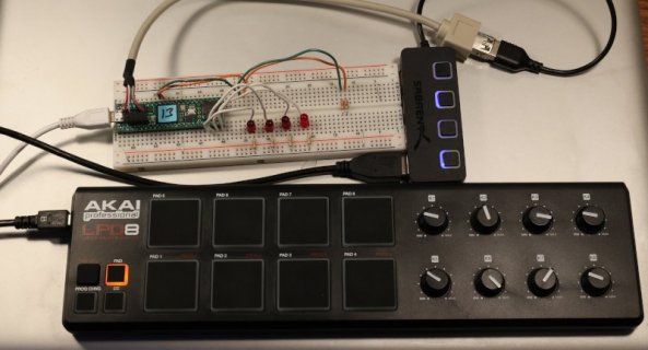
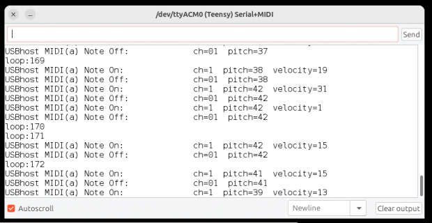
PaulStoffregen replied to the thread Teensy 4.1 hang up when using USBHost_t36.h with HUB to control multiple midi device.I ran your program from msg #1. I made only 1 small modification to print "loop <number>" slowly because the note on/off messages scroll off screen too quickly (full code below). static elapsedMillis msec; // print at a reasonable pace if...
-
-
PaulStoffregen replied to the thread U2 and D4 hot, 3.3v shorted to GND.This is a really strange case. Normally when a board goes badly and consumes too much current for things to get really hot, either the 5V power or the 3.3V power measures low. But you said you measured 4.7V and 3.3V. Normally when a large...
-
PaulStoffregen replied to the thread Teensy 4.1 How to start using DMA?.Maybe this can help? https://forum.pjrc.com/index.php?threads/queued-triantaduows2811-a-32-channel-ws-library-for-teensy-4-0-using-flexio-dma.59023/
-
PaulStoffregen replied to the thread Button press output errors - assistance needed.Try setting Tools > CPU Speed for slower, like 150 MHz or even 24 MHz. Quick and easy way to test if running too quickly for signals to stabilize.
-
PaulStoffregen replied to the thread Audio library depends on SdFat.Yes, you're right, something in these libraries is causing unused code to be compiled into the final binary. I've added this to my low priority bug list. Just to set expectations, this is a low priority if everything works properly and the only...
-
PaulStoffregen replied to the thread Connecting Teensy 4.0 to HC-05 module.Sure. Teensy 4.0 has 7 serial ports. 5 of those are one the easy-to-access pins. Just connect the other modules to any of the other serial ports and then replicate your code for the other 2. Ok, maybe it won't be quite the simple. You'll...
-
PaulStoffregen replied to the thread Configurable usbMIDI Port Names.I am not aware of any way, at least from code running on Teensy. I did try this by editing descriptors. For Serial it is possible to affect the name shown on MacOS and Linux, but not Windows (because it ignores the descriptor name and gets the...
-
PaulStoffregen replied to the thread digital input.You should probably run some tests with that Kingbright LED. The specs say brightness is 10 to 25 mcd with 10 mA current. Maybe a lower current will meet your needs, or maybe not. Only you can make that judgement call. If you need a...
-
PaulStoffregen replied to the thread New Teensy 4.0 Suddenly Not Recognized.Try the 15 sec restore. Hold the pushbutton for 13 to 17 seconds. At 13 sec, you'll see the red LED blink briefly to indicate you're at the beginning of the 4 sec window where releasing the button causes full memory wipe and restore of a...
-
PaulStoffregen replied to the thread U2 and D4 hot, 3.3v shorted to GND.On Teensy or pretty much any circuit board, if you have a large current flowing an unknown path, one thing you can do is measure voltage drop along the power and ground. You'll need a multimeter with sensitive mV scale. Then just touch any 2...
-
PaulStoffregen replied to the thread U2 and D4 hot, 3.3v shorted to GND.This is quite weird indeed. Is this Teensy actually working, like you can load new programs and they run correctly?
-
PaulStoffregen replied to the thread U2 and D4 hot, 3.3v shorted to GND.Try measuring the 3.3V voltage while the power is on the input parts are hot. Do not rely on ohms measurement. If the voltage is very low, only several mV, that's a sure sign the short is metal. Usually these problems can be fixed if you find...
-
PaulStoffregen replied to the thread Pulse counter using Teensy 4.0.I tried to look up the minimum pulse width needed for the GPIO interrupt hardware, but couldn't find it in NXP's documentation. But as a general rule of thumb, usually 2 clock cycles are needed because they almost always use a circuit that...
-
PaulStoffregen replied to the thread Pulse counter using Teensy 4.0.The ADC inside Teensy is far too slow for this type of narrow pulse. You will need to handle this as a 3V a digital signal. A voltage comparator is probably the best way, but TL714 is probably too slow. I'd recommend trying a faster chip, like...
-
PaulStoffregen replied to the thread Best way to implement complicated mix of PWM and interrupt?.I also have no understanding of the context here which makes answering difficult. (the reason I haven't replied to the latest questions) @rootwyrm - Have you actually connected the signals to your Teensy 4.0 or 4.1 and experimented yet? Maybe...
-
PaulStoffregen replied to the thread USB connection from D+ / D- pins with external supply.Try replacing all the wires carrying the USB signals with short lengths of real USB cable. Don't use ordinary hookup wire for D+ or D- anywhere, not even for short lengths. Even if all the wires are real USB cable, the use of non-USB connectors...
-
PaulStoffregen replied to the thread Teensy 4.1 function call order in setup() affects the flow of code.Well, this was just a guess. But it fits the facts you mentioned, that the code had worked on a previously used Teensy 4.1 but failed when you tried on a new Teensy 4.1. The uninitialized contents of emulated EEPROM would be a likely...
-
PaulStoffregen replied to the thread USB connection from D+ / D- pins with external supply.When you edit usb.c, first try adding any simple syntax error. Then click Verify. Arduino IDE should notice the file changed and recompile. Seeing the syntax error quickly confirms Arduino really is recompiling the code and you really are...
-
PaulStoffregen replied to the thread USB connection from D+ / D- pins with external supply.Earlier I believed you had cut a USB cable and soldered its wires directly to the pads on the bottom side of Teensy 4.1. I assumed that from words "not from a USB cable connected to the D+ / D- and GND pins". But in this photo, it is not a USB...
-
PaulStoffregen replied to the thread Teensy 4.1 function call order in setup() affects the flow of code.Just a guess, maybe one of those other functions does not like the scenario where INDEX_ADDRESS or DEVICE_ID_ADDRESS is a number like 255 (the uninitialized EEPROM value)?
-
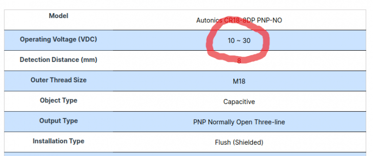
PaulStoffregen replied to the thread digital input.The website for that sensor says the minimum power is 10 volts.
-
-
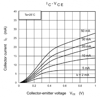
PaulStoffregen replied to the thread digital input.Now I see how it should work. :) The LED and 300 ohm resistor should connect between the collector and 3.3V. When the optocoupler turns on the collector is pulled to GND by the NPN phototransistor. So for the LED to show on condition, connect...
-
-
PaulStoffregen replied to the thread [posted] Teensy-RV-Leveling-Helper.Posted on the website https://www.pjrc.com/rv-leveling-helper/
-
PaulStoffregen replied to the thread [posted] Programmierbarer WS2812B LED-Strip Controller.Posted on the website https://www.pjrc.com/ws2812b-led-controller/
-
PaulStoffregen replied to the thread Anti-spam effort in 2024 - Please report spam quickly when you see it.I tried setting the edit time limit to 5 hours. Hopefully that gives enough time to fix typos or technical errors, but stops spammers from turning their odd but acceptable AI generated messages into obnoxious spam.
-
PaulStoffregen replied to the thread uploading hex file via teensy loader.I'm not very familiar with Windows. I mostly use Linux. On Linux, certain characters are special and need quotes so the command line doesn't parse them and instead passes the info directly to the program. Maybe Windows command line is similar...
-
PaulStoffregen replied to the thread uploading hex file via teensy loader.Maybe Arduino IDE is printing that error? Teensy software has only English language.
-
PaulStoffregen replied to the thread uploading hex file via teensy loader.Maybe you could show us the exact error, as either copy & paste of the text, or a screenshot if the text can not be easily copied?
-
PaulStoffregen posted the thread Anti-spam effort in 2024 - Please report spam quickly when you see it in General Discussion.Spam is rising again. Reporting spam quickly really does help! If you see spam, please report it. Speed matters. Just writing "spam" in the report is fine, no need for more. Reports affect more than just 1 message. If the spammer has...
-
PaulStoffregen replied to the thread digital input.I don't understand your schematic. You said you are using "a Capacitive Proximity sensor". But on the schematic, I see only resistors, capacitors, diodes, a quad optocoupler, a connector, and net names that imply connection to other stuff we...
-
PaulStoffregen replied to the thread Teensy 4.0 Board Unresponsive After USB Disconnection.First check if your program has something like "while (!Serial)" in setup. This is common in most example programs, to wait for the Arduino Serial Monitor so you don't miss any Serial.print() info. But if left in your final code, it will just...
-
PaulStoffregen replied to the thread About expansion to RAM1.The solution is to add FLASHMEM to some of your code, so it doesn't use RAM1, and/or to add DMAMEM to some of your arrays so they are allocated in RAM2 rather than RAM1. RAM1 is faster than RAM2, and *much* faster than flash. But both RAM2 and...
-
PaulStoffregen replied to the thread 4.1 failure after steady operation.4 blinks usually means an issue with the crystal. Might be a good idea to inspect that area for debris or leftover flux from soldering nearby pins.
-
PaulStoffregen replied to the thread USB connection from D+ / D- pins with external supply.If you don't find the solution, try taking some photos so we can actually see. Might help, might not. Worst case you waste just a few minutes to shoot photos and transfer (maybe resize) so they can be posted here. Many times on this forum a...
-
PaulStoffregen replied to the thread Best way to implement complicated mix of PWM and interrupt?.Maybe you meant input pin? With output pins, which you control with analogWrite(), you should already know the setting because your code set it. If you need to later have this info, just store it into a variable which you can later use. But to...
-
PaulStoffregen replied to the thread Best way to implement complicated mix of PWM and interrupt?.You might also consider using analogWriteFrequency() in setup(), so your PWM outputs are at the specific frequency you want. Details here: https://www.pjrc.com/teensy/td_pulse.html I see you wrote "written identically to pin 28 and pin 29". I...
-
PaulStoffregen replied to the thread Best way to implement complicated mix of PWM and interrupt?.I don't understand why you would call analogWrite() every time loop runs. The PWM output will continue updating indefinitely, so you need to call analogWrite() when you want to change the output. Likewise, why delay for 1 second? You'll only...
-
PaulStoffregen replied to the thread USB connection from D+ / D- pins with external supply.This really should work. Any chance the wire colors aren't matched up to the corresponding pins inside the cable? (for example, white and green really connected to GND and +5V)
-
PaulStoffregen replied to the thread U4 Chip gets extremely hot when 4.1 is connected to power..Unfortunately, no. Nobody can really give a clear definitive answer about what happened, or even might have happened. First, we just don't know enough. We can't see what type of motor you're using. Maybe it's something very small like on this...
-
PaulStoffregen replied to the thread Teensy 4.1 How to start using DMA?.OctoWS2811 on Teensy 4 is probably the most complicated DMA of any library. You'd probably be better off reading the DMA code from a much simpler library, like WS2812Serial. To answer this specific question, 16K is the distance between each of...
-
-
PaulStoffregen replied to the thread PWM Voltage Conversion.I don't understand the reluctance to use a proper 5V tolerant buffer chip. For 3 signals, you'd need 1 chip and 1 decoupling capacitor for good quality results. Seems better than using 6 parts for marginal quality waveforms.
-
PaulStoffregen replied to the thread PWM Voltage Conversion.This circuit has some limitations which may or may not be a problem. Understanding the issues can help you to anticipate whether it will work well enough, or if those limitations will cause problems. The main issue is the diode's forward...
-
PaulStoffregen replied to the thread Two queues on i2s input not working.Yes, this is expected behavior. If you leave any record queue active but your program doesn't remove the data, incoming audio quickly uses up the available memory. It is not a bug in the audio library. This is the way queues work.
-
PaulStoffregen replied to the thread ShiftPWM library compile error.I've committed a fix on github. https://github.com/PaulStoffregen/ShiftPWM/commit/4c25bfda72ac3cb99fc20ae7cb8c35aa8926e363 Sadly, this library isn't tested by my script that tries to compile all examples from all libraries because these...
-
PaulStoffregen replied to the thread Two queues on i2s input not working.If you want me to investigate, please post another complete program to demonstrate the problem. Even if the change from the code you showed in msg #5 is trivial, I need you to understand I have a long history of wasting time not able to...
-
PaulStoffregen replied to the thread Two queues on i2s input not working.For the sake of testing, I'd try allocating many more blocks, like 100. Then if you see your usage is in the 90s, you'll know one or more of the queues is hogging memory.
-
PaulStoffregen replied to the thread Two queues on i2s input not working.Try using AudioMemoryUsage() to monitor how many of the 10 audio memory blocks are used up. Or use AudioMemoryUsageMax() to check whether you have at any point used up all the memory. My guess, admittedly from only a quick glace at your code, is...
-
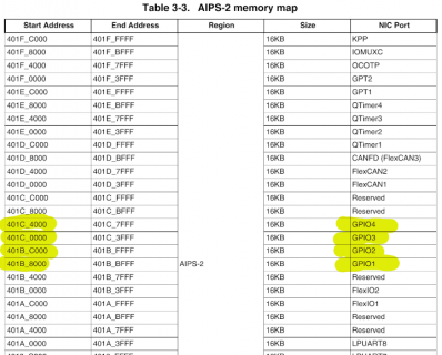
PaulStoffregen replied to the thread Running a timer off an external clock signal on Teensy 4.1?.To configure the input pins, you'll need to write to the mux registers and also the select input registers. IOMUXC_SW_MUX_CTL_PAD_GPIO_AD_B1_02 IOMUXC_SW_MUX_CTL_PAD_GPIO_AD_B1_03 IOMUXC_SW_MUX_CTL_PAD_GPIO_AD_B1_04...
-
PaulStoffregen replied to the thread Running a timer off an external clock signal on Teensy 4.1?.One small gotcha... before you access any of the GPT2 registers, enable its clocks by setting the CCM_CCGR0_GPT2_BUS and CCM_CCGR0_GPT2_SERIAL bits in the CCM registers.
-
-
Loading…
-
Loading…