PaulS
- Messages
- 1,740
- Reaction score
- 60
Latest activity Postings About
-
-
 PaulS replied to the thread Trouble getting rotary encoder to work with Teensy 4.0.Yes, there are so many rotary encoders out there that knowing which one is mandatory. You may want to have a look at this thread and this thread for using rotary encoders with NPN output stage. Paul
 -
PaulS replied to the thread Wake on USB?.Looking further into the Snooze libary, I ran into the SnoozeUSBSerial example. Apparently you can use USB Serial output but it's not a wake-up source. So the USB interface is actually active in Sleep mode. Forum member @duff might be able to...
-
PaulS replied to the thread Wake on USB?.I'm not 100% sure, but isn't the USB interface inactive while in Sleep mode? Paul
-
PaulS replied to the thread Communicated with ADC122S101 chip using SPI.You may want to open an issue at https://github.com/RobTillaart/ADC08XS/issues. Rob Tillaart is very responsive and actually this current issue might be relevant to you. Paul
-
PaulS replied to the thread snooze example code does not compile (reduced_cpu_block).Line 7 of the example states Supported Micros: T-LC/3.x. Since the writer of the Snooze library is also a forum member here, you could try to PM him @duff . Paul
-
-
attachInterrupt(digitalPinToInterrupt(drumPin1), playDrum1, RISING); much better :)
-
PaulS reacted to PaulStoffregen's post in the thread Forum server suffering from a denial of service attack with
 Like.
It's really not a lot of total data transfer. The units are incorrect. Numbers at the last 2 lines are total bytes, not per second. 8.7 GB over 24 hours, if it repeated every day, would add up to only 1.3% of the server's 20TB monthly...
Like.
It's really not a lot of total data transfer. The units are incorrect. Numbers at the last 2 lines are total bytes, not per second. 8.7 GB over 24 hours, if it repeated every day, would add up to only 1.3% of the server's 20TB monthly... -
PaulS replied to the thread v trigger and arduino code.I'm wondering what library you are actually using. Ah, I think you are using the AudioSynthSimpleDrum class from the Audio library. Like Pete said, please post your code. Paul
-
PaulS replied to the thread Best Long Term speed for Teensy 3.5.From the K64 datasheet: My recommendation would be: if can you run at 100Mhz, do so - it lowers the overall powerconsumption and perhaps it improves reliability. Paul
-
-
PaulS replied to the thread Any tips / suggestions or experience having solutions manufactured w/ a Teensy?.Since you are mentioning Ethernet, I assume you are talking about the Teensy 4.1, correct? For a 100pcs series, I would consider using low-profile IC sockets like this: You would need to purchase the Teensy 4.1 with soldered pins and Ethernet...
-
-
PaulS replied to the thread TEENSY 4 LED PIN 13 AS INPUT.Yes, the sending Teensy is perfectly capable of driving the on-board LED on the receiving Teensy, so there are no problems to expect with respect to reliability. The same applies the other way around: a Teensy outputting a digital signal on pin...
-
PaulS replied to the thread Inserting boards into prototyping adaptors.@AussieBruce You may want to consider purchasing BusBoard breadboards. I used to use breadboards that you can buy everywhere but have seen the same problems you described. But when I threw away all those cheapo breadboards and purchased a bunch...
-
-
PaulS replied to the thread Using TRS MIDI input.Maybe these pages will help you to decide how to connect the Amazon boards: All you need to know about TRS MIDI connections and A simplified guide to TRS MIDI. Paul
-
PaulS replied to the thread Teensy 4.1 custom board Not detected com port.I think you only need to replace the bootloader chip, and not the IMXRT microcontroller & not the flash memory chip because you started with an empty bootloader chip. I assume that nothing has paired yet. From the bootloader page: But I would...
-
PaulS replied to the thread Analog input not Sending controller message.Well, glad you found that! If you want to check for MIDI output, this online tool may be useful as well. Paul
-
PaulS replied to the thread Analog input not Sending controller message.Insert a Serial.println(n1); to check the analog reading, like so: if (msec >= 20) { msec = 0; int n1 = analogRead(A1) / 8; //CC 11, expression Serial.println(n1); // insert here if (n1 != previousA1) {...
-
PaulS replied to the thread Teensy 4.1 custom board Not detected com port.This thread & thread may be helpful. Paul
-
PaulS replied to the thread Teensy 4.1 custom board Not detected com port.As far as I understand it, you won't be able to get a compatible cloned Teensy board. Remove your chip and replace it with a chip purchased from PJRC. Paul
-
PaulS replied to the thread Teensy 4.1 custom board Not detected com port.The bootloader chip @KurtE referred to, must be a PJRC-programmed version. If you purchase the chip from PJRC [this one for Teensy 4.1], it is programmed with the required functionality. Paul
-
PaulS replied to the thread USB B to midi to the teensy.What kind of keyboard are you meaning, a QWERTY or MIDI keyboard? Indeed, a Teensy doesn't have a physical MIDI port - you have to add that to the Teensy as explained here. Paul
-
PaulS replied to the thread AD9833 Success With TFT-Touch And T4.1.Not really a driver but this is the code I used successfully an a Teensy LC: #include <SPI.h> // pin 13 (SCK), pin 11 (MOSI), AD9833 generator #define FSYNC 10 // pin 10 (SS) #define SPI_CLOCK_SPEED...
-
PaulS replied to the thread Teensy 3.2 to Teensy 4.0 - no longer working.In the schematic, I only see a diode between VCC and the input of the 5V regulator? What is VCC actually? 12V? Is the output of the regulator indeed 5V as intended? Paul
-
PaulS replied to the thread Teensy 3.2 to Teensy 4.0 - no longer working.I'm a bit confused: you stated "As soon as I plug in the power, the light immediately turns off and it no longer shows up on ArduinoIDE". So did the Teensy show up in the Arduino IDE when only USB was plugged in? Paul
-
PaulS replied to the thread Teensy 3.2 to Teensy 4.0 - no longer working.So when it's powered by USB only, Teensy is working fine? The display doesn't show of course. I assume you cut these pads and placed a Schottky diode: Can you share a photo of this placed diode? Paul
-
-
PaulS replied to the thread Teensy 3.2 to Teensy 4.0 - no longer working.One of the important differences between Teensy 3.2 and Teensy 4.0 is that the pins of a Teensy 3.2 are 5V tolerant. Teensy 4.0 pins are definitely not 5V tolerant. Could it be this is at play? Looking at the schematic I would say this is not...
-
PaulS replied to the thread teensy 4.0 + audio board "Compilation error: exit status 1".A "Compilation error: exit status 1" could be caused by a lot of different issues. You may want to switch on full verbose output in the Preferences window: And then share what you see in the Output window. Interestingly, your code compiled fine...
-
-
PaulS replied to the thread MIDIfy a 13 note pedalboard.You will need to connect a common wire from one side of each switch to the GND pin on the Teensy. The other side of each switch needs to be connected to an individual Teensy pin. Then use the pinMode(pin, INPUT_PULLUP); to pull the signal high...
-
PaulS replied to the thread Teensy 4.0 / High Voltage Heater.You're absolutely right, it's like this: Paul
-
-
PaulS replied to the thread Teensy 4.0 / High Voltage Heater.Yeah, finally! Who would have imagined that by shifting the enable bit 1 position to the left makes the whole thing work... well, you did apparently! Sigh, so much for a correct datasheet. Are you going to feedback this to them or just be happy...
-
-
PaulS replied to the thread Teensy 4.0 / High Voltage Heater.Hmm, strange results. Tomorrow, I will hookup my SK Pang LIN-Bus Breakout Board and check with the oscilloscope as well. With respect to the use of the CSS CL1000: I don't think it's usable since it is a CAN bus logger only. Paul
-
PaulS replied to the thread Teensy 4.0 / High Voltage Heater.Hi Jordan, the fight apparently isn't over yet... I'm not sure what to think about the ID27 results. But first I would like to focus on sending data to the heater to get it running. Since he suggested this: I pulled the logic analyzer out and...
-
-
PaulS replied to the thread Teensy 4.0 / High Voltage Heater.Hi Jordan, that flowchart helped a lot to clearify. In the flowchart below I noted the register IDs in red. I skip reading out status register ID27 for now. So we have to write ID33 first , then ID22 and then finally ID22 again. Below the...
-
-
PaulS replied to the thread Teensy 4.0 / High Voltage Heater.Hi Jordan, thanks for the new info. I will look into it over the coming weekend. Paul
-
PaulS replied to the thread 关于怎么学习学习Tensy 3.2."How to systematically learn Tensy 3.2 and code" Best to start with the tutorial. Paul
-
PaulS replied to the thread Teensy 4.0 / High Voltage Heater.Like a kind of brute-force attack? Hmm, too many possible input combinations to my taste. And how to verify the output? What came to mind though is whether there is a requirement on how to apply the voltages timing-wise. Like 12V first to get...
-
PaulS replied to the thread Teensy 4.0 / High Voltage Heater.Agree, reading ID17 is not required for the heater to activate. I was hoping that only writing ID22 & ID33 would be enough to kick off the heater. Paul
-
PaulS replied to the thread Teensy 4.0 / High Voltage Heater.I'm a bit lost though - I wonder if we are doing something fundamentally wrong in the LIN communication to the heater, because what we see doesn't make sense. Well, I do hope the supplier will come back with some sort of initialisation sequence...
-
PaulS replied to the thread Teensy 4.0 / High Voltage Heater.That CRC: 104 is correct with both data bytes being 0x00:
-
-
PaulS replied to the thread Teensy 4.0 / High Voltage Heater.I think CRC 255 means error?
-
PaulS replied to the thread Teensy 4.0 / High Voltage Heater.ID33 is a really a 2 LIN data byte message. It's a typo from their side. From the specs: They probably better stop using the word 'byte'; we are talking 'registers' here with a certain bit length. What does "with a byte length of 3 bytes"...
-
-
PaulS replied to the thread Teensy 4.0 / High Voltage Heater.Hi Jordan, Looked further into the odd/even number of databytes. Several sources [incl Wikipedia] state that the number of bytes must be 2, 4 or 8. However when studying the LIN 2.1 spec, no such requirement is there. So last night I contacted...
-
-
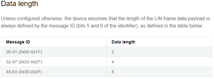
@jsimonkeller: I'll jump in, in case you're looking for a quick turn-around on an answer. You correctly converted (hex) 0x20 to (binary) 00100000. In the binary representation of any hex number, no bits need to either be rearranged and/or...
-
PaulS replied to the thread DS1820 rod sensor.You may want to select a DS18B20 since the DS1820 is obsolete. Yes, see this tutorial. From a reputable source in your country. The latter sounds good. Paul
-
PaulS replied to the thread Teensy 4.0 / High Voltage Heater.Hi Jordan, sorry, we cannot bypass the LIN roadblock. The heater only accepts LIN data for control... What the engineer stated is: "We execute PWM control through software, not through external low-voltage wire for PWM signal control". And then...
-
-
PaulS replied to the thread Teensy 4.0 / High Voltage Heater.From the answer of the engineer and re-reading the spec, my understanding is as follows: 1. We can not drive the heater by an external PWM signal. There is no analog or PWM pin available on the Low voltage connector. 2. Internally, the heater...
-
PaulS replied to the thread Teensy 4.0 / High Voltage Heater.Thanks for forwarding the response from the engineer. On the E2E checksum and E2E counter values, since he is talking only about read-register 0x34 ["In this project, only the 0x34 message has the above two fields"], I think we're fine with...
-
-
I've started a CrashReport documentation page. https://www.pjrc.com/teensy/td_crashreport.html Hopefully no surprises, but now we'll have an official permalink page for the CrashReport documentation.
-
Thanks Paul. Sorry I didn't understand the issue with checksum. I am wondering if the key again will be the "enable" command in 0x33 and confirming if it worked. I will say that one item I was able to decode from the received data that made...
-
PaulS replied to the thread Please help me, it's urgent..How do you conclude that the Teensy reboots? And what do you exactly mean by "ceases to function properly"? Does it refuse to reboot and run your code again? Very detailed description of the behaviour does help! Can you do the Memory Wipe as...
-
PaulS replied to the thread Teensy 4.0 / High Voltage Heater.Hi Jordan, the whole LIN-bus checksum stuff is clear and handled properly by the library. The checksum I was looking for is the one in register ID33. In message #151 I wrote: Unfortunately both documents do not shine any additional light on the...
-
-
Loading…
-
Loading…