P
Pio
Well-known member
- Joined
- Messages
- 96
- Reaction score
- 82
Latest activity Postings About
-
-
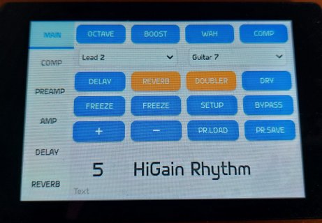
PPio replied to the thread Stereo guitar/bass cabinet emulation.GUI work is so time consuming... Expression pedal controlling the wah and updating the corresponding slider on the display: https://streamable.com/1jml92 BOOST section is renamed to PREAMP and contains wah + boost + octave up now. Also the...
-
-
PPio replied to the thread quick question about Audio Shield inputs.Audio Shield has 2.2uF decoupling capacitors present on the Line input L & R. It is safe to run the DC output of the MEMS board to either Line input L, R or both. AC output of the MEMS board will also work. In this case the effective decoupling...
-
PPio replied to the thread Stereo guitar/bass cabinet emulation.More work on the Wah section: the implementation is based on the work by Transmogrifox https://cackleberrypines.net/transmogrifox/src/bela/inductor_wah_C_src/ adapted to the current TGX4 workflow (mono processing, bypass is stereo) and with a...
-
PPio replied to the thread Stereo guitar/bass cabinet emulation.@tomas Thank you! It's been a journey and i think it will go further. Having the tested hw base i'll try to run the NAM models on Teensy next. While researching this topic lately i found a few PCB pics of the IK ToneX pedal, which, surprise...
-
PPio replied to the thread Stereo guitar/bass cabinet emulation.The 3 band tone stack (AMP section) is independent and always on. There is also a global high pass filter at the end of the signal chain. I need to somehow squeeze the wah into the gui now. I think i'll change the Booster tab to "Preamp" and it...
-
PPio replied to the thread Stereo guitar/bass cabinet emulation.What this project was still lacking is a decent wah, not only for the usual "quack" sounds, but also as a pre EQ tone shaping tool. Adding it now. I'm not after modelling any specific models, but rather using one as a starting point and tweak it...
-
PPio replied to the thread Stereo guitar/bass cabinet emulation.I'm still deep in the GUI(ESP32) - Teensy integration. Preset System: supports up to 128 presets (if SD card is present) or 8 if using EEPROM only. EEPROM is still used to hold the 1st 8 presets. Acts like a backup copy, SD cards can fail...
-
PPio replied to the thread TeensyThreads causes errors building in Platform.IO.Maybe this will help - undef the compiler flags in the platformio.ini file https://docs.platformio.org/en/stable/projectconf/sections/env/options/build/build_unflags.html
-
PPio replied to the thread Issues with custom audio object.Also disabling the interrupts globally within the update/triggerGrain, which happens inside the audio interrupt is probably not a good idea.
-
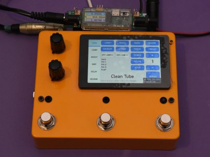
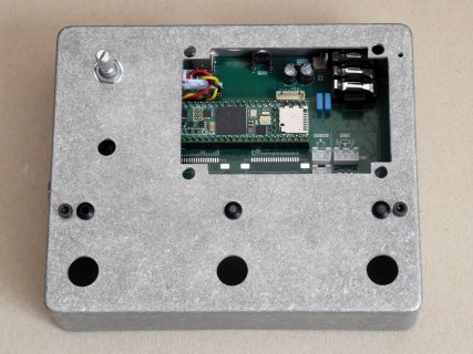
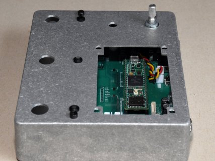
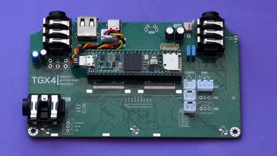
PPio replied to the thread Stereo guitar/bass cabinet emulation.Before the ESP starts to talk to Teensy i wanted to see if everything works when put together into the enclosure, check the current consumption. Teensy + ESP32S + Display (not using any wireless connectivity yet) draws about 217mA from a 9VDC...
-
-
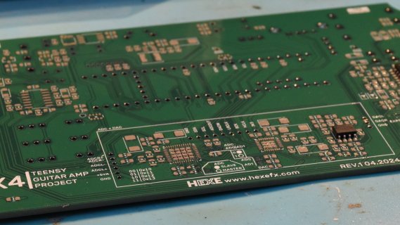
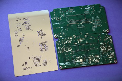
PPio replied to the thread Stereo guitar/bass cabinet emulation.Thanks! Noise/oscillation issues are almost gone with the AK converters. I have used the stencil + solder paste and human pick&place. For placing the components i use either tweezers (larger components) or a vacuum pick up which i designed...
-
-
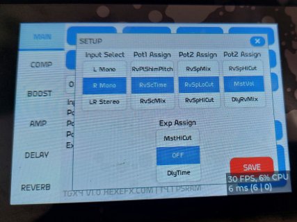
PPio replied to the thread Stereo guitar/bass cabinet emulation.WebMIDI (fx settings) + WebSerial (console + status report) in the browser, MIDI+Serial over USB for the Teensy. The GUI on the pic above is a platformio native linux project for LVGL9.1 which then will be run on the ESP32+TFT. ESP will control...
-
PPio replied to the thread Stereo guitar/bass cabinet emulation.On the GUI side: there is one main tab with quick access to the most used functions plus preset handling. All sections have their tabs with all the controls from the html page.
-
-
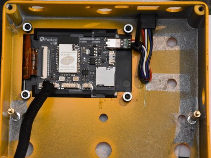
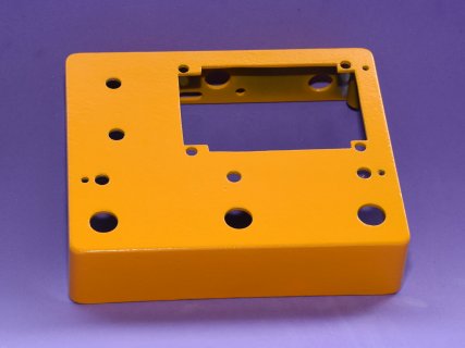
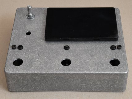
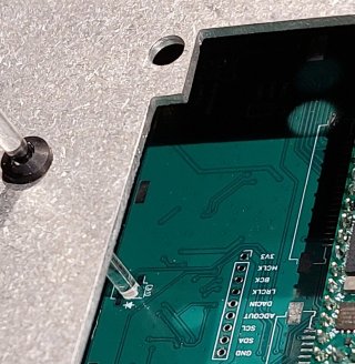
PPio replied to the thread Stereo guitar/bass cabinet emulation.Working on the enclosure now. Everything fits as planned. For the light pipes i'm going to use a 3mm round acrylic rods mounted into a LED bezels.
-
-
PPio replied to the thread Stereo guitar/bass cabinet emulation.Got the AK5552+AK4452 working with 32bit/44.1kHz. The difference is huge. Practically zero oscillation and much lower noise. Here is a visual comparison of the hi gain preset 5 output, inputs are shorted to GND:
-
-
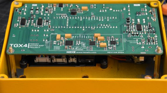
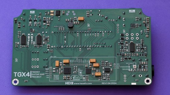
PPio replied to the thread Stereo guitar/bass cabinet emulation.Progress update: populated two boards, one used as testing bed for each circuit block and the other as "final". No major hiccups so far, added only a few changes, nothing requiring board reorder (which was not cheap - 4 layers over 100mm). Also...
-
-
PPio replied to the thread Stereo guitar/bass cabinet emulation.Hi Chip, i tried both HPF settings. Somehow i couldn't reproduce the issue on all of my hardware (not using the Teensy Audio board). Although i did have issues with SGTL5000 going into crazy self oscillation, they were power decoupling related...
-
PPio replied to the thread Stereo guitar/bass cabinet emulation.Boards arrived, now let's hope there will be no or minimal need for bodges.
-
-
-
Loading…
-
Loading…