S
sndsgd
Member
- Joined
- Last seen
- Messages
- 21
- Reaction score
- 6
Latest activity Postings About
-
-
SIn cases like this, I often look at the most recent products with the schematic. With the T4.x it is the Sparkfun MicroMod If you look at their Schematic: So probably why they have the label DEBUG_EN
-
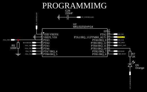
Ssndsgd replied to the thread MKL02Z32 required pins.My main hesitation around connecting it is that I don't know if doing that will have some sort of impact on the sdram functionality. This snippet from the hardware design guide is what is causing my anxiety: The SDRAM interface (running at up to...
-
SI'm working on a custom PCB with SDRAM loosely based on @Dogbone06's deboard v5 and I'm trying to decipher exactly which MKL02 pins are required for a teensy 4.x compatible pcb. The pin in question is `PTA1/IRQ_1`, which routes to the...
-
-
SYou only need to add pullup or pulldown resistors if you're going to have a "dumb" USB-C port (without any voltage negotiation). When using a controller like the IP6520 you just connect the lines directly to the IC.
-
Ssndsgd replied to the thread Call to arms | Teensy + SDRAM = true.@Dogbone06 did you make any updates to accomodate this comment? I'm looking at what I believe is the last version of the schematic/pcb posted, but I think i need to connect cc1, cc2, dp, and dm from L10 (the IP6520) to USB2 as in this schematic...
-
-
Ssndsgd replied to the thread Call to arms | Teensy + SDRAM = true.Whoops, I just realized the significance of 10x10. It looks like the devboard should use the DVL6B variant of the chip? It looks like that is available at both Mouser and Digikey, so perhaps a rework attempt is still possible?
-
Ssndsgd replied to the thread Call to arms | Teensy + SDRAM = true.Thanks for the details. It sounds like the assumption right now is that using the ...DVJ6B chip variant available on the PJRC store and elsewhere on the internet would address the issue, but that particular variant is less available (or just not...
-
Ssndsgd replied to the thread Call to arms | Teensy + SDRAM = true.Hey folks, any update on how the v5 devboards turned out? Is everything working as expected? I'm about to head down the dual frame buffer + elcdif rabbit hole, and given @Rezo 's success I'm thinking the lastest schematic/pcb posted in this...
-
SThanks that's exactly what I was looking for! :D
-
Ssndsgd replied to the thread 60Hz+ display refresh rate?.You can definitely get well over 60fps at 16bit color with an ILI9341 using https://github.com/vindar/ILI9341_T4. That said, the true frame rate (and how "solid" it is) will come down to how much detail you have per frame, and how you go about...
-
Ssndsgd replied to the thread Call to arms | Teensy + SDRAM = true.Keeping a single thread for the general ideas and then kicking off new threads for more specific projects seems to make sense to me. This thread is a good read, and I think it's about to get a lot better very soon 😀
-
Ssndsgd replied to the thread Call to arms | Teensy + SDRAM = true.Mind if I ask how you're manufacturing these? I'm particularly curious about the MKL02 chip. Are you manually adding the chip from the PJRC store after having the rest assembled at JLCPCB?
-
Ssndsgd replied to the thread Call to arms | Teensy + SDRAM = true.Ah ha! The bottom layer strikes again!
-
Ssndsgd replied to the thread Call to arms | Teensy + SDRAM = true.I use 1uf, but please take that with a grain of salt. I'm just a hobbyist! On another note, I'm looking over the schematic and pcb, and I can't find U4 (W25Q128JVPIM) on the pcb. This is my first time using easy eda, so please forgive me if its...
-
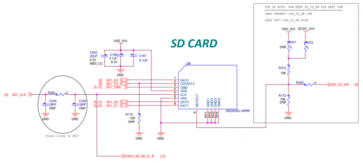
Ssndsgd replied to the thread Call to arms | Teensy + SDRAM = true.@Dogbone06 have you tested the sdcard on a previous generation? I'd expect a decoupling capacitor at the sdcard 3.3v pin would improve reliability 🤔
-
Ssndsgd replied to the thread Call to arms | Teensy + SDRAM = true.It looks like you already have these: AD_B1_00 AD_B1_01 AD_B1_02 AD_B1_06 AD_B1_07 AD_B1_08 AD_B1_09 AD_B1_10 AD_B1_11 AD_B1_15 That would make these pins the missing ones from the GPIO_AD_B1 bank: AD_B1_03 AD_B1_04 AD_B1_05 AD_B1_12 AD_B1_13...
-
Ssndsgd replied to the thread How to connect SD card reader to teensy 4.0 through pads?.FWIW I've had success using blackketter/teensy4_header_breakout (forum post here) as a starting point for making my own PCB to get access to the SD_* pins via a surface mounted teensy 4.0: I was surprised by the quality of the castilated holes...
-
-
Ssndsgd replied to the thread Anti-spam effort in 2024 - Please report spam quickly when you see it.WRT post editing time limit, it looks like this might be the setting you're looking for: https://xenforo.com/community/threads/edit-post-time-limit.49152/
-
-
Loading…
-
Loading…