Audio Tutorial Assembly Issue

lhouse36

New member
I’ve been attempting to assemble and use the teensy audio tutorial from the unbuilt audio tutorial parts and I've been running into some issues trying to pass the hardware test.

Using the hardware test program, I’ve been able to get the standard beeps from the serial monitor but the buttons and knobs don’t register inputs, and the knob inputs appear to come somewhat inconsistently when the board is moved, but I cannot figure out what potential loose connections could be causing this issue. I checked the schematic placements for the wires quite a few times. Does anybody know of any common errors in doing this kind of assembly that could be causing this issue or if there’s anything present in the attached images?

I apologize if there's something I may have absolutely gutted in this assembly, I'm very much new to this.

IMG_4046.jpgIMG_4045.jpgIMG_4047.jpg
 
You probably need to work on your soldering technique. Many great tutorials exist. Here's on from Sparkfun (scroll past all the sales pitch stuff).

https://learn.sparkfun.com/tutorials/how-to-solder-through-hole-soldering/all

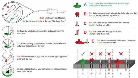
This graphic is the really important part.

solder.jpg

Looks like you ended up with "B" from this diagram. The good news is you can probably still redo the soldering to get to something closer to "A".

The main beginner mistake is being too shy to apply heat. You need to get the iron tip physically touching the PCB pad. Looks like you might have touched only the pin. You also need to leave it in contact long enough while you feed in the solder, so the solder melts and fully whets to both the pin and PCB pad surface. This takes time, like 1 second or more. But be shy about heat. After you have fed in the solder (and withdrawn it), leave the iron in contact so everything fully heats up.

Don't pull the solder and iron away at the same moment. Remove the (cold) solder first and leave the iron in contact for a moment. Getting all the parts fully heated is critical.

The other key ingredient is flux. This is a chemical inside the solder. It can also be purchased in liquid form, but if you do this, be sure to get flux that matches the solder you use (eg, don't mix rosin with organic acid types). The flux together with heat cleans the oxidation off of the metal surface, which is critically important to getting a good result. The smoke you see while soldering is the flux and surface oxidation burning off.

The absolute last thing you should do is try applying the solder only to your iron and then touch the metal, because the flux only get on your iron and doesn't end up cleaning the metal surfaces. This is why you first touch your iron to the metals (maybe with only a tiny amount of residual solder on the iron's tip) and then feed in the solder. As you feed the solder in, you're also delivering the flux chemical.

Soldering is a skill that takes some learning and practice. Everyone has to start somewhere. Hopefully this message helps. I'm pretty sure you can fix this with another try, just remember the main beginner mistake is being too shy about heat. You have the leave the iron in contact long enough for both metal parts and all the solder to fully heat up, and for the flux to clean the metals enough.
 
Thank you for the help!

I tried re-soldering to make it more clean, trying to follow the directions a little bit better and I think it's a bit more fixed up. It has almost no random knob inputs anymore when moved around now, but it still not registering inputs from the buttons or knobs. Do you think this soldering is still the issue or do you think it might be another problem?

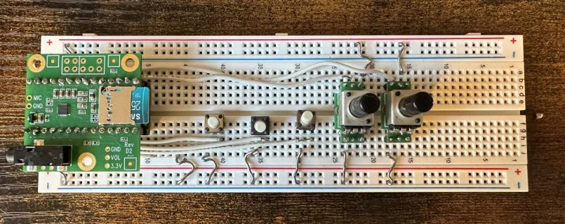
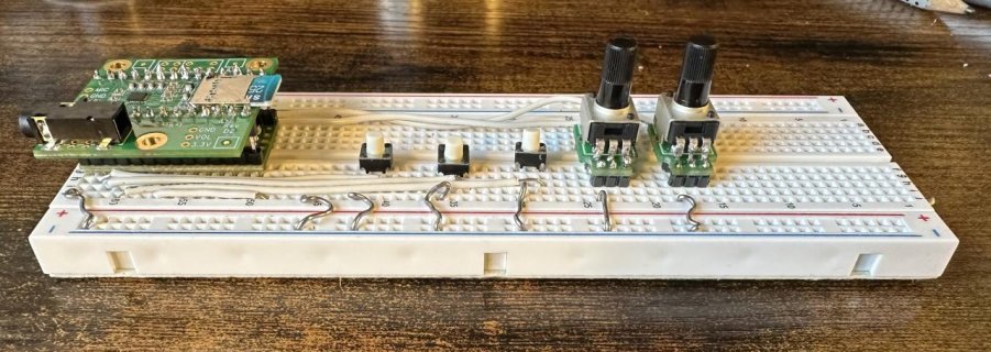
IMG_4049.jpgIMG_4050.jpgIMG_4051.jpg
 
Forum rule?

Also those button switches don't look properly seated - in fact many button switches are not designed for breadboard and don't really reach down to the contacts.
 
The soldering is definitely looking better. Did you also remember to solder the stacking header on the bottom side of the Teensy to complete the connections?
 
This tutorial explains how to troubleshoot pushbuttons (and it was recently updated for Teensy 4.0).

https://www.pjrc.com/teensy/tutorial3.html

The connection used by the audio tutorial is the "Built In Pullup Resistor" way described near the end of that page.

I'd start with a voltmeter, like the pushbutton tutorial shows. Of course make sure your Teensy 4.0 is running a program which configures those 3 pins with INPUT_PULLUP mode. Then measure the voltage on each pushbutton wire. If the solder connection to Teensy 4.0 is good, you should see 3.3V because of the pullup resistor inside the chip. If you get 0 volts even when the button isn't pressed, that's a sure sign the wire isn't really connected to the Teensy pin. Photos look like you have the wire in the correct place on the breadboard, so no connection to the Teensy pin probably means more soldering to touch up.
 
Back
Top