Hi Everyone,
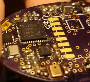
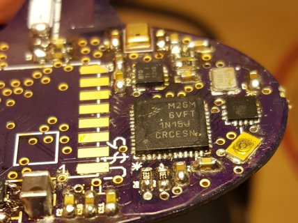
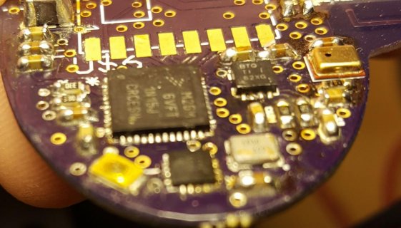
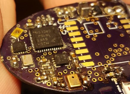
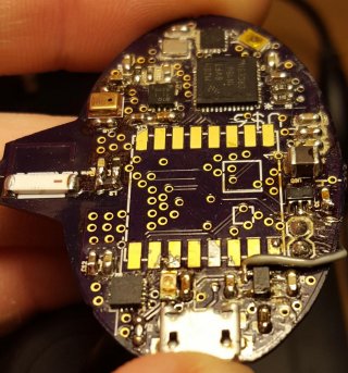
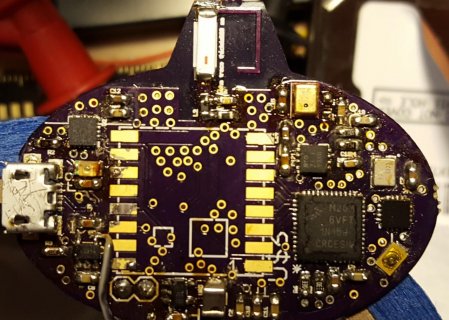
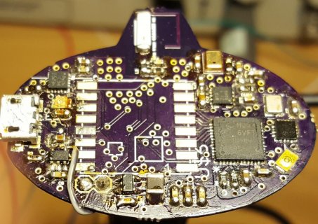
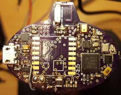
I am attempting my first custom Teensy. In this case, I am using an MKL26Z64VFT4 just like the Teensy LC, instead of the 3.1 (which is what I see people debugging most often on the forums).
I have been able to get to the point where I can see the MK02 sending signals to the MKL26 followed by the oscillator booting up. However, I don't see anything on the USB lines. When I inspect them with an oscilloscope I see almost nothing. There is a little bit of deterministic noise (as if singnals are coupling into the USB lines) but no external signals to the Teensy are moving at all.
Things I have examined:
- I am using an external regulator so VREGIN is tied to VDD (there is no VBATT pin on the LC).
- The oscillator has no switching signals crossing under it. I could improve the ground ring slightly but the osc. running.
- I have tried powering this from a bench power supply with al of the other high-power components removed.
- I have manually gone through the pinouts to make sure signals are connected properly on the board.
- I have checked for shorts and open pins and everything is checking out.
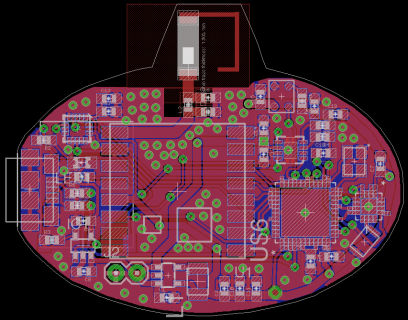
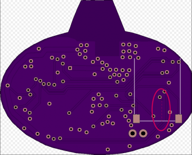
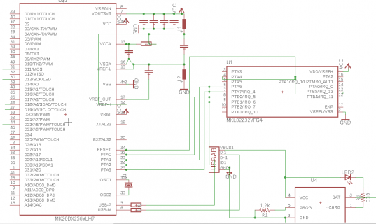
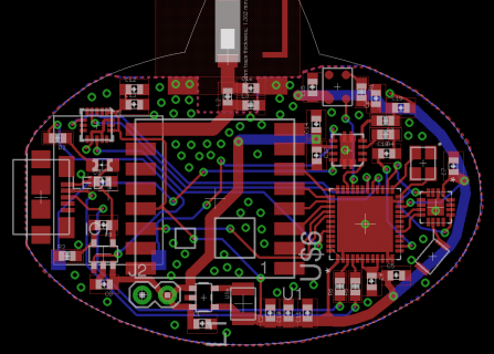
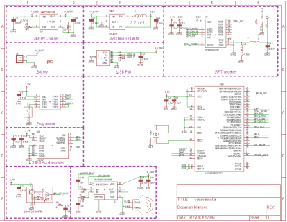
I have attached my schematics and board layout. I would appreciate it if anyone has any ideas about what to try next.
Thanks,
Joe
 View attachment communicator.pdf
I am attempting my first custom Teensy. In this case, I am using an MKL26Z64VFT4 just like the Teensy LC, instead of the 3.1 (which is what I see people debugging most often on the forums).
I have been able to get to the point where I can see the MK02 sending signals to the MKL26 followed by the oscillator booting up. However, I don't see anything on the USB lines. When I inspect them with an oscilloscope I see almost nothing. There is a little bit of deterministic noise (as if singnals are coupling into the USB lines) but no external signals to the Teensy are moving at all.
Things I have examined:
- I am using an external regulator so VREGIN is tied to VDD (there is no VBATT pin on the LC).
- The oscillator has no switching signals crossing under it. I could improve the ground ring slightly but the osc. running.
- I have tried powering this from a bench power supply with al of the other high-power components removed.
- I have manually gone through the pinouts to make sure signals are connected properly on the board.
- I have checked for shorts and open pins and everything is checking out.
I have attached my schematics and board layout. I would appreciate it if anyone has any ideas about what to try next.
Thanks,
Joe
 View attachment communicator.pdf


