Hello.
I have been trying to get this DAC80502-01 evaluation Board to output a signal other than zero.
In the the 8051 datasheet, it states that the CS pin needs to stay low for at least 24 clock cycles, otherwise it goes into sync interrupt mode which sets the DAC output to zero.
"For SPI-mode operation, the SYNC line stays low for at least 24 falling edges of SCLK and the addressed
DAC register updates on the SYNC rising edge. However, if the SYNC line is brought high before the 24th
SCLK falling edge, this event acts as an interrupt to the write sequence. The shift register resets and the write
sequence is discarded. Neither an update of the data buffer or DAC register contents, nor a change in the
operating mode occurs."
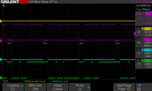
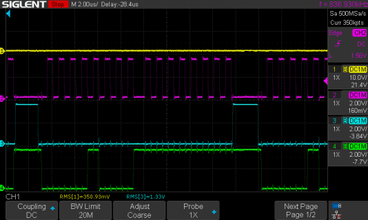
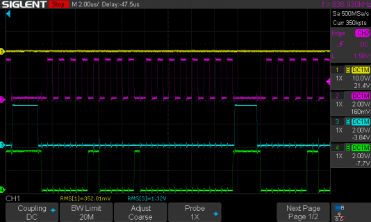
Looking at my oscilloscope pictures. After the CS pin goes low, I only get 16 clock cycles before the CS pin goes high again.
You can see in the picture that it writes the command bit to the DAC. but it only writes the MOSI data for 8 clock cycles Instead of the desired 16.
How can I fix this please?
Any help will be most appreciated. Thank you.
Yellow trace is DAC out.
Pink trace is SCLK.
Blue trace is CS.
Green Trace is MOSI.
I have been trying to get this DAC80502-01 evaluation Board to output a signal other than zero.
In the the 8051 datasheet, it states that the CS pin needs to stay low for at least 24 clock cycles, otherwise it goes into sync interrupt mode which sets the DAC output to zero.
"For SPI-mode operation, the SYNC line stays low for at least 24 falling edges of SCLK and the addressed
DAC register updates on the SYNC rising edge. However, if the SYNC line is brought high before the 24th
SCLK falling edge, this event acts as an interrupt to the write sequence. The shift register resets and the write
sequence is discarded. Neither an update of the data buffer or DAC register contents, nor a change in the
operating mode occurs."
Looking at my oscilloscope pictures. After the CS pin goes low, I only get 16 clock cycles before the CS pin goes high again.
You can see in the picture that it writes the command bit to the DAC. but it only writes the MOSI data for 8 clock cycles Instead of the desired 16.
How can I fix this please?
Any help will be most appreciated. Thank you.
Yellow trace is DAC out.
Pink trace is SCLK.
Blue trace is CS.
Green Trace is MOSI.
Code:
// set pin 10 as the slave select:
const int slaveSelectPin = 10;

uint8_t  device_ID_command = 0x01;
uint16_t device_ID = 0x0115;
uint8_t  trigger_command = 0x05;
uint16_t soft_reset = 0x000A;
uint8_t  dac_out_command = 0x08;

uint16_t dac_data = 0xFFFF;


void setup() {
  Serial.begin(9600);
  pinMode (slaveSelectPin, OUTPUT);
  digitalWrite (slaveSelectPin, HIGH);
  SPI.begin();
  spi_Write(trigger_command, soft_reset); // software reset
  delay(10);
  spi_Write(device_ID_command, device_ID); // Device ID
  delay(10);
}

void loop() {
      dac_data = 0xFFFF;
      spi_Write(dac_out_command, dac_data);
      Serial.print(" dac_data ");
      Serial.println(dac_data, HEX);

      dac_data = 0x0000;
      spi_Write(dac_out_command, dac_data);

      Serial.print(" dac_data ");
      Serial.println(dac_data, HEX);
}

void spi_Write(uint8_t command_byte, uint16_t data_byte) {

  SPI.beginTransaction(SPISettings(1000000, MSBFIRST, SPI_MODE0));//4000000
  // take the SS pin low to select the chip:
  digitalWrite(slaveSelectPin,LOW);
  //  send in the address and value via SPI:
  SPI.transfer(command_byte);
  SPI.transfer(data_byte);
  // take the SS pin high to de-select the chip:
  digitalWrite(slaveSelectPin,HIGH);
  SPI.endTransaction();

  //Serial.print(" command_byte ");
  //Serial.print(command_byte, HEX);
  //Serial.print(" data_byte ");
  //Serial.print(data_byte, HEX);
}