Stewieman01
Member
Hi all,
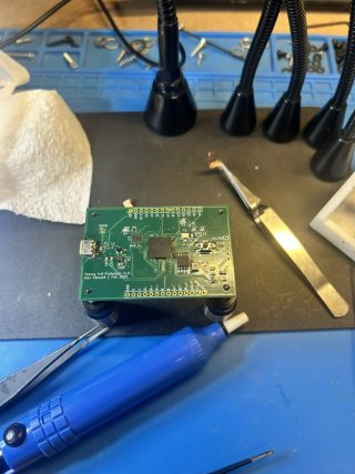
I created a custom PCB following the Teensy 4.0 schematic and have assembled it, however when testing the board it gets stuck in the power up sequence and no 3.3V is outputted from the regulator. i have tried replacing the chip and making sure there are no short circuits between the pads and i have even completely remade the board with all different parts. This resulted in it having a different symptom, being the 3.3V regulator heats up rapidly. i cant figure out the reason physically in my soldering and i cant spot any issues in the schem or pcb layout myself. i understand the power up sequences steps however from my checks everything seems correct, but clearly its not.
I wanted to ask to see if anyone with more experience than me would be able to help me determine the potential issue. The Github repo for the kicad files are here and have provided a pdf for the schem as well. any help would be appreciated, thanks!