TelephoneBill
Well-known member
I had need recently to see if I could generate a very precise 81 KHz signal using a Teensy 3.5. I was looking for precision much better than 1 Hz.
This frequency is employed by Radio Station GYN2, which co-incidentally happens to have the tallest man made structure in the UK - an antenna with a height of 365 metres.
81 KHz is a very unusual frequency to create from a Teensy. The peripheral clock frequency of 60 MHz does not lend itself kindly for driving an FTM timer by a simple direct division ratio.
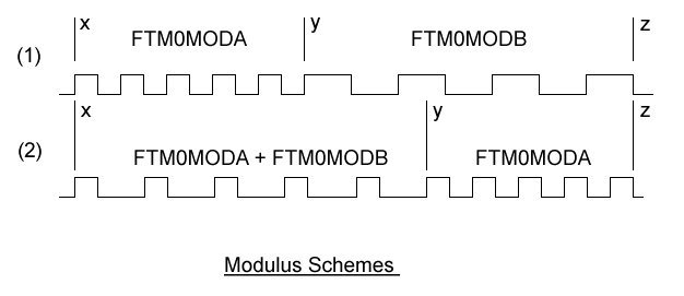
After a few experiments, I found that the best way to do this was to use the "dither" principle, which entails hopping from a frequency just below 81 KHz to another just above 81 KHz and back again (ad infinitum). If this switching is done fast and at the correct rate, then the "average frequency" of a Teensy square wave can be made to appear to be a very precise 81 KHz. This "dithering" will create some jitter on the generated signal edges, but if this jitter is acceptable then the problem can be solved in this way.
The project code for this experiment is included below. I use the dither switching in two distinct ways. First, to switch the MODULUS of timer FTM0 between two adjacent values, and second to switch digital capacitors that control the Teensy 16 MHz crystal itself. The first is a form of coarse frequency adjustment, and the second is very fine adjustment.
The dither switching is performed inside the Interrupt Service Routine (ISR) that is fired every time the FTM timer count rolls over from the MODULUS value to zero. By changing the modulus quickly at the start of the ISR, then its register will already have been updated ready for when the counter needs to make the value comparison at the top end of the count. I use Channel 2 of the FTM0 timer for my own convenience, but another channel could easily be used instead.
To allow for dynamic adjustments, I can enter values for the switching points (on a scale of 0 to 999) by entering keystrokes via the serial monitor. For example, typing "i500<CRLF>" will set the ISRCount at 500, which is mid scale for the MODULUS factor. Typing "i501<CRLF>" will nudge the frequency upwards slightly, or "i499<CRLF>" will nudge it downwards.
Using a GPS signal as a reference, and typing new values by trial and error, then the 81 KHz output frequency can be gently nudged to be better than 1 Hz. Similarly, by typing "x500<CRLF>" etc. then very fine adjustments can be made way less than 0.1Hz.
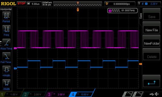
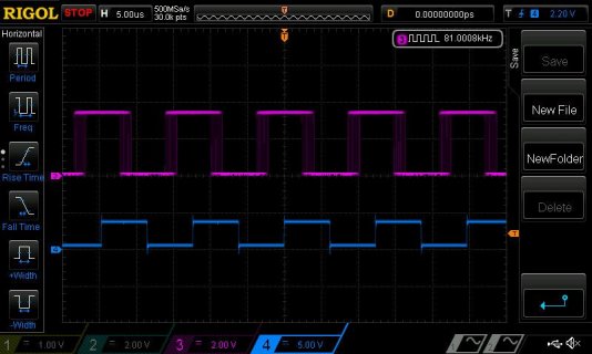
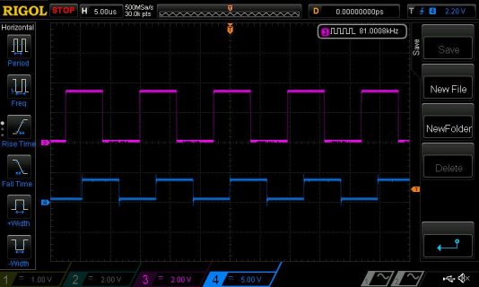
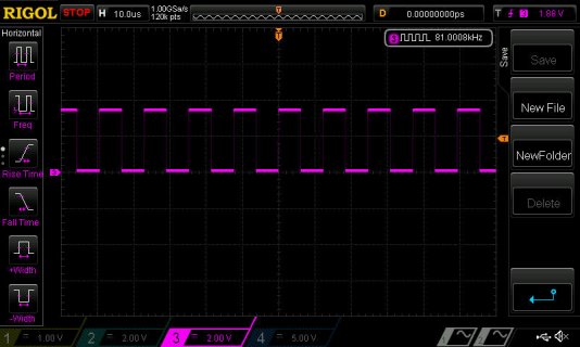
The picture shows just how good this technique works (but you can't see the jitter). My scope frequency counter is in known error by 1 part in 10e5, so that "8" on the end of "81.0008 kHz" is actually correct.
When dealing with extreme precision of this nature, it has to be remembered that control will be temperature dependant. Don't expect to set the frequency exact on one day, and find it the same the next day. But it won't be far off

Code:
//Teensy35 - Eighty One KHz Experiment
//====================================
//Date: Mon 05 AUG 2019 - Experiments with precision 81 KHz (version 02)
//CPU speed 120 MHz = 60 MHz Peripheral Clock speed (16.667 nS cycle).
//Uses Teensy 3.5. FTM page in Reference Manual - Page 783.
//K64 Signal Multiplexing - Para 10.3.1 Page 246.
//Require two cycles of FTM0 for one cycle of 81 KHz, hence "then divide by 2" in modulus calculations

//Declarations
//------------
#include <stdint.h>
volatile unsigned int FTM0MODA, FTM0MODB, ISRCount, ISRAdjust, XtalCount, XtalAdjust, OneSecCount;
byte Byte1, Byte2, Byte3, Byte4;
boolean Toggle;

//Set Up routine
//--------------
void setup() {
  Serial.begin(9600);             //setup serial port
  delay(1000);

  //initialise Flextimer 0
  FTM0MODA = 369;       //369 = 370 - 1 (1st Modulus for FTM0). 60,000,000 divided by 370 and then divided by 2 = 81.081081 KHz
  FTM0MODB = 370;       //370 = 371 - 1 (2nd Modulus for FTM0). 60,000,000 divided by 371 and then divided by 2 = 80.862534 KHz
  FTM0_MODE = 0x05;     //set write-protect disable (WPDIS=1) bit to modify other registers. FTMEN = 1.
  FTM0_SC = 0x00;       //set status/control to zero = disabled (enabled in main loop)
  FTM0_MOD = FTM0MODA;  //set modulus to initial value
  FTM0_C2SC = 0x14;     // CHF=0, CHIE=0 (disable interrupt, use software polling), MSB=0 MSA=1, ELSB=0 ELSA=1 (output compare - toggle), 0, DMA=0
  FTM0_C2V = 0;         //compare value = 0 for CH0

  PORTA_PCR5 |= 0x300;  //MUX = alternative function 3 gives FTM0_CH2 = toggle output on Teensy Pin 25

  //enable FTM interrupt within NVIC table
  NVIC_ENABLE_IRQ(IRQ_FTM0);

  //lower Systick priority and raise IRQ_FTM priority
  SCB_SHPR3 = 0x20200000;             //Systick = priority 32 (default was zero - highest priority)
  NVIC_SET_PRIORITY(IRQ_FTM0, 0);     //raise FTM0 IRQ to priority 0

  //enable external clock on FTM0, no prescale
  FTM0_SC = 0x48;       // (Note - FTM1_SC [TOF=0 TOIE=0 CPWMS=0 (Up Counting only) CLKS=01 (Peripheral Clock) PS=000 (no prescale divide)]

  //initialise variables
  pinMode(13, OUTPUT);    //pin 13 (LED) as digital output
  ISRCount = 0;
  XtalCount = 0;
  XtalAdjust = 500;
  ISRAdjust = 629;
  FTM0_MODE = 0x04;       //FTMEN = 0 (cannot alter FTM0_MOD inside ISR when FTMEN = 1)
}


// ISR routine for FlexTimer0
//---------------------------
//(Triggered by FTM0 timeout on each Cycle)
//FASTRUN puts this code into RAM to run twice as fast
//Serial Monitor: type i123<CRLF> to set ISRAdjust to "123", type x123<CRLF> to set XtalAdjust to "123"
FASTRUN void ftm0_isr(void) {
  //ISR latency time = 200 nanoSecs after interrupt flag set by FTM1 Timer Overflow
  FTM0_SC &= ~FTM_SC_TOF;             //clear overflow flag

  //test which FTM0_MOD value to use - dither between these two values to get exact 81 KHz output frequency from FTM0 toggle output
  if (ISRCount<=ISRAdjust) {
    FTM0_MOD = FTM0MODA;              //higher output frequency (81.081081 KHz)
  }
  if (ISRCount>ISRAdjust) {
    FTM0_MOD = FTM0MODB;              //lower output frequency (80.862534 KHz)
  }

  //update ISR counter (dither scale 0 to 999)
  ISRCount++;                         //increment ISRCount
  if (ISRCount>=1000) {               //counter beyond max value (999)
    ISRCount = 0;                     //therefore reset ISRCount
    OneSecCount++;                    //also, increment one sec counter
    if (OneSecCount>=162) {           //162 is twice 81 (KHz), so times 1000 gives a one second pulse
      OneSecCount = 0;
      Toggle = !Toggle;
      digitalWriteFast(13, Toggle);   //blink the LED on/off every second
    }
  }

  //This following code will make incremental frequency adjustments circa 1Hz and below (on a scale 0 to 999)
  //adjust peripheral clock freq via digital capacitors if reached XtalAdjust value
  if (XtalCount<XtalAdjust) {         //counter reached point to change digital capacitor
    OSC0_CR = 0x04;                   //faster digital capacitor setting (0x04 = +26.661 ppm)
  }
  else {
    OSC0_CR = 0x02;                   //slower digital capacitor setting (0x02 = -3.109 ppm)
  }

  //update XtalCount (dither scale 0 to 999)
  XtalCount++;                        //increment XtalCount
  if (XtalCount>=1000) {              //counter beyond max value (999)
    XtalCount = 0;                    //therefore reset XtalCount
  }
}


//Main Loop
//---------
void loop() {
  //read key input (if any)
  KeyInput();                         //read key input (if any)
}


//KeyInput Routine
//----------------
void KeyInput() {
  //process any keystrokes available
  if (Serial.available()>0) {
    //read the incoming byte
    Byte1 = Serial.read();
    if (Byte1>0x20) {
      switch (Byte1) {
      case 'x':  //x123 - set XtalAdjust
        if (Serial.available()>=3) {
          Byte2 = Serial.read();
          Byte3 = Serial.read();
          Byte4 = Serial.read();
          XtalAdjust = ((Byte2-0x30) * 100) + ((Byte3-0x30) * 10) + ((Byte4-0x30) * 1);
        }
        Serial.print("XtalAdjust = ");
        Serial.println(XtalAdjust);
        break;
      case 'i':  //i123 - set ISRAdjust
        if (Serial.available()>=3) {
          Byte2 = Serial.read();
          Byte3 = Serial.read();
          Byte4 = Serial.read();
          ISRAdjust = ((Byte2-0x30) * 100) + ((Byte3-0x30) * 10) + ((Byte4-0x30) * 1);
        }
        Serial.print("ISRAdjust = ");
        Serial.println(ISRAdjust);
        break;
      case 'a':  //a123 - set FTM0MODA
        if (Serial.available()>=3) {
          Byte2 = Serial.read();
          Byte3 = Serial.read();
          Byte4 = Serial.read();
          FTM0MODA = ((Byte2-0x30) * 100) + ((Byte3-0x30) * 10) + ((Byte4-0x30) * 1);
        }
        Serial.print("FTM0MODA = ");
        Serial.println(FTM0MODA);
        break;
      case 'b':  //b123 - set FTM0MODB
        if (Serial.available()>=3) {
          Byte2 = Serial.read();
          Byte3 = Serial.read();
          Byte4 = Serial.read();
          FTM0MODB = ((Byte2-0x30) * 100) + ((Byte3-0x30) * 10) + ((Byte4-0x30) * 1);
        }
        Serial.print("FTM0MODB = ");
        Serial.println(FTM0MODB);
        break;
      } //end of switch statement
     } //end of Byte1 > 0x20
  } //end of if Serial Available
}

