Help for Understanding the Grounding Pins on Teensy 3.2 for Midi Controller

JJJ

Member
Hi!

I am trying to build a version of this Teensy 3.2 Sketch and midi-controller circuit that I found online;

https://llllllll.co/t/17-diy-teensy-midi-controller/28539

It's basically just a USB Midi Controller with 17 rotary potentiometers.

I am new to Micro-Controllers and am just trying to figure all of this out.

I imported the circuitboard into a demo of EagleCAD so I could see the schematic, as it is not shown on the GitHub for the project.

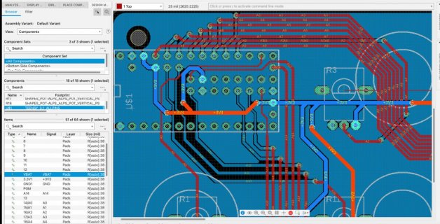
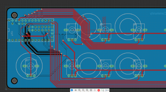
I sort of get how each potentiometer is connected for one of it's pin's, and I see a ground pin shared by all the pots, but don't see how the third pin is connected on each potentiometer?

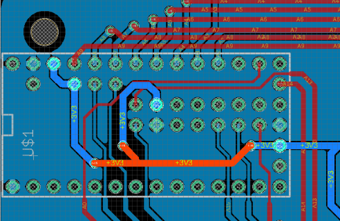
Also there seems to be inter-connections between pins on the Teensy board itself ("ARef" or something else?) and I don't understand if this is already a default for the Teensy board or what this is doing or if it's necessary?

Thanks!
Screenshot 2023-08-11 at 09.15.10 AM.png

Screenshot 2023-08-11 at 09.14.53 AM.jpg

Screenshot 2023-08-11 at 09.31.42 AM.png
 
but don't see how the third pin is connected on each potentiometer?
The third pins are connected to +3V3. Look closely at R3 in the middle image above.

Also there seems to be inter-connections between pins on the Teensy board itself ("ARef" or something else?)
Yes, Teensy 3.2 has 2x 3.3V pins connected on the board, 2x GND pins connected on the board and an AGND pin [analog GND].
You can check the schematic here.

Paul
 
Hi thanks you so much for your kind reply!

Please excuse my beginner's ignorance with all of this...I'm trying to learn how these work and this is my first project.

I'm going to read through what you wrote a few times and look at and read the link you kindly sent me.

Looking at the link for a minute, at first I thought it was a schematic built with the Teensy, but this must be the schematic of the Teensy board's ("inner"? "inter"?)-connections and components?

One more question if you don't mind?

The "3.2 has 2x 3.3V pins connected on the board, 2x GND pins connected on the board and an AGND pin [analog GND]"...are these all discrete, or are the pairs connected hard-wired together?

Thanks again!
 
but this must be the schematic of the Teensy board's ("inner"? "inter"?)-connections and components?
Correct, it's the schematic of the Teensy board with the internal signal connections between the different on-board components and the pins that form the interface to the outside world. That big rectangle with 'MK20DX256VLH7' is the microcontroller itsself that does the heavy lifting.

The pairs 3.3V and GND are hard-wired together on the board. In general, if you see the exact same signal name twice or three times on the schematic, you can safely assume these are connected together.

Paul
 
Hey THANKS !!!!!!!!!!!!!!!!!!!!!!!!!!!!!!!!!!!!!!!!!!!!!!!!!!!!!!!!!!!!!!!!!!!!!!

I really appreciate your help!!!
 
Some general advice on your project: if you indeed want to build this MIDI controller based on a Teensy 3.2, please check whether you can actually purchase a T3.2. They are extremely scarce because that actual NXP microcontroller is still suspended from manufacturing as far as I know.
You will see/read/hear that a Teensy 4.0 is the proper replacement. But be aware that a Teensy 4.0 only has 14 analog inputs...

Paul
 
Hi thanks again!

I actually bought the 3.2 at the start of Covid planning on learning about them, and of course became to busy with work and am finally getting around to it (2? 3?) years later.

I actually did find a project for Teensy 2.0 that would better fit my needs but was unsure if I could just use a 3.2 instead of the 2.0.

The 2.0 project has five faders and multiple momentary switches, and project this has lots of faders but no momentary switches.

I think when I get further in to this I'll try to figure out how to add a momentary switch to type an alphanumeric (not a midi-message) to punch in and out of record.

Thanks again for all of your kind help!
 
Hi I did start to build this but ran into a problem.

I uploaded the sketch to the Teensy 3.2, attached only one potentiometer and one momentary SPST switch, and then plugged it in to my DAW.

I get all of these random midi controller cc's (it looked like their the specific midi controller #s that are in the sketch) spewing constant messages into the DAW.

I was thinking maybe it's because I don't have all of the momentary-switches and pots in the circuit yet?

How would I test this and get it to work without wiring ALL of the switches and pots?

In the end, I just want 5 pots and one momentary switch.

How would I connect stuff to be able to make it work when I don't have every switch or pot in the whole circuit?

Many thanks!!!
 
Unconnected digital inputs should have pull-ups or pull-downs enabled so they don't float (probably already the case for momentary switch inputs), analog inputs for pots must have their voltage defined, perhaps just tie they temporarily to GND, or comment them out in the code for now.
 
Unconnected digital inputs should have pull-ups or pull-downs enabled so they don't float (probably already the case for momentary switch inputs), analog inputs for pots must have their voltage defined, perhaps just tie they temporarily to GND, or comment them out in the code for now.

Hi thanks for that. That explains why I had all of the weird bursts of midi cc's.

We are on vacation now, and when we get back I'll pu the code up.

Many thanks!
 
Back
Top