Help me measure VREF on teensy 3 and 3.1

Status
Not open for further replies.

gripner

Well-known member
Hello all
Sorry for starting a new thread, but last one got jacked.

I need some help from some one with a high res volt meter.
Need to have the aref value measured when the teensy3/3.1 is powered via a USB. And then move the teensy around between differetn USB ports/puters to see how much the vraf differ. if any
My initial tests points to this beeing the case, but i need it confirmed.

thanks in advance.

Leif
 
Are you wanting to investigate the 1.2 volt internal reference, or changes on the 3.3 volt power supply when using external reference?
 
Sorry if it was unclear,

The internal I assume is imposible to measure, well since it is internal.

I want to measure the external, via the 400 suming ohm resistor
 
Ok, I'm trying a few measurements...

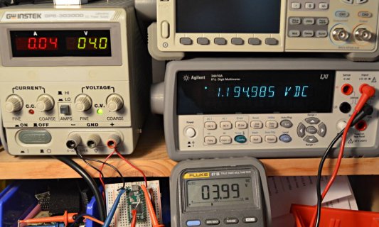
VIN = 5.00 volts, AREF(ext) = 3.26749 AREF(int) = 1.194974

VIN = 3.99 volts, AREF(ext) = 3.26099 AREF(int) = 1.194985

VIN = 3.604 volts, AREF(ext) = 3.25737 AREF(int) = 1.194972

VIN = 3.198 volts, AREF(ext) = 2.86699 AREF(int) = 1.194962

I used an Agilent 34410A multimeter to measure AREF. It was set to the slowest, highest resolution mode: "100 NPLC" (whatever that means....) This particular 34410A is about 3 years old and has not ever been recalibrated, so it's outside the recommended 1 to 2 year calibration interval. Hopefully these 8 measurements can at least be compared to each other, even if the meter itself if outside Agilent's recommended calibration interval.

I physically moved the positive lead between the AREF pad and a small wire I soldered directly to pin 17, to access the 1.2V internal reference voltage. Both were measured with the negative lead to AGND.

I used a Fluke 87-III multimeter to measure VIN, relative to GND. The power came from GwInstek power supply.

Here's a photo of the test setup.

vref_test.jpg
(click for full size)
 
Paul -- 'NPLC' is number of Power Line Cycles -- the number of 50/60 Hz cycles over which it measures -- this filters the effects of interference picked up from AC power lines. So 100 PLC takes 100/60 = 1.67 seconds per measurement.

Your measurements on AREF(int) are within the specified range (1.195 V +/- 0.2 %).

The AREF(ext) is not intended to be accurate -- it is also operating within specifications. From VIN falling from 5 V to 4 V, it changed by less than 7 mV, or also 0.2 %

0.2 % represents about 2 counts on a 10-bit ADC conversion.
 
Thanks for the help! Calibrated or not a neet instrument for sure!

As I expected the vreg on the teensy board differ on its output ever so slightly. Your measurement is quite much bigger in difference than the USB that can differ +/-5 percent or so. but its enough when you read with a high resolution adc as the teensy 3 and 3.1 have. As Jp 3141 stated, its about 2 counts in a 10bit adc conversion when going down from 5V to 4V so if the USB voltage differ 5% of 5V its 0,25V or so, it should be quite a inpact when reading with 16bit.

Thanks again.

Could a way to overcome this be to simply use a voltage devider to get around 3.2V and feed vref (removeing the 400ish ohm pullup on the teensy board), the voltage devider is feed via the same powersorce (probobly a LM7808) that is driveing the loadcell and instrumental amplifier? Depending on "input powers voltage" the LM7808 will just as the onboard vref not be 100% acurate, but if it change the vref will change aswell.

Or perhaps simply drive the loadcell of the 5v usb line? The volatge to the loadcell will differ in different USB ports/computers, but the vref will also. altho the vref most likely differ alot less.... Im thinking wrong ?
 
As Jp 3141 stated, its about 2 counts in a 10bit adc conversion when going down from 5V to 4V so if the USB voltage differ 5% of 5V its 0,25V or so, it should be quite a inpact when reading with 16bit.

Could a way to overcome this be to simply use a voltage devider to get around 3.2V and feed vref (removeing the 400ish ohm pullup on the teensy board), the voltage devider is feed via the same powersorce (probobly a LM7808)

As the measurements showed, the ARF(ext) changes somewhat (10mV) when the input voltage changes a lot (1.4V). That ratio of input voltage change to output voltage change is called Power Supply Rejection Ratio (PSRR). Here, the PSRR is 0.7%.
Notice that then the input voltage falls below a certain minimum, the regulation is lost. That happens in the last measurement, we get a 400mV change for a change in input of 1.8V (PSRR = 22%)

The PSRR of a voltage divider is very poor - for example a 1:1 divider has a PSRR of 50% - change the input by one volt and the output at the junction of ther two resistors changes by 0.5V (the ratio of the risistors in the divider).

In contrast, the AREF(int) changed by 12μV (0.000012V) when the input changed by 1.8V. That is a PSRR of 0.00067%. The internal reference is created by a specialized circuit called a voltage reference, which is designed to have a very high PSRR (and also a high rejection of changes in response to load, over some fairly small load range).

If you want better PSRR than AREF(ext) and the voltage provided by AREF(int) is not suitable, you have a couple of options. One is to use an extra ADC channel to simply read AREF, or better, to read AREF/2. That allows you to scale your other ADC readings to a constant AREF.

Another option is to use a voltage regulator (such as the LM7808) as a voltage reference, as you suggest. However, a voltage regulator is less stable than a voltage reference. It usually has worse PSRR and worse drift over temperature. (It can typically supply a lot more current, athough the voltage does change a bit with increasing current - this is Load Regulation).

A third option is an external voltage reference chip to provide a stable voltage with high PSRR. These chips are available with a range of voltages - 5, 4.096, 3.3, 3.0, 2.5 and 2.048 are commonly available. Fior circuitry that draws little current, you can use these directly as miniature power supplies. For slightly higher current, an op-amp buffer on the voltage reference output helps.
 
That's actually the best way to do this type of application -- ultimately you are looking for a ratio of resistances, not any particular voltage value; so any practical value of voltage reference would work just as well.

So as long as you use the same voltage reference to power the sensor bridge and to set the ADC's reference, you're OK.

You'll still be limited by noise pickup, resistor drift and thermocouple effects.
 
Ok lets try this again!, just hit Reply to thread instead of Post quick reply and erased my entire post!

In my thread AGND or GND http://forum.pjrc.com/threads/25868-AGND-or-GND I was looking into why my ADC measurements of a fixed voltage changed when i eighter touched the PC connected to the teensy or changed the USB-port the teensy was conected to!

I tried to use LFP, decoupling caps as well as with help of forum members with alot more knowlage then me use the AGND vs GND correctly.

Non of this helped! So I suspected the 3.3V-reg was not able to filter out the high freq garbage on the USB 5V power line.
This is the case, i have cut the 5V line and feed the teensy via a LM7805. now the value say 10000 changes around 1-2 digit when I change USB-port or touch the computer.

So Paul, even tho the fault is more on the PC-side with garbage on the USB power line, is there a possibility to add filter/better 3.3v-reg on the teensy3/3.1 that can handle the crap on the USB powerline.
The reason I ask is that i use/will use alot of teensy 3.1 units and do not fancy cutting the pads under the board. Neighter design in a LM7805 + its caps.
 
Ok, I'm trying a few measurements...

VIN = 5.00 volts, AREF(ext) = 3.26749 AREF(int) = 1.194974

VIN = 3.99 volts, AREF(ext) = 3.26099 AREF(int) = 1.194985

VIN = 3.604 volts, AREF(ext) = 3.25737 AREF(int) = 1.194972

VIN = 3.198 volts, AREF(ext) = 2.86699 AREF(int) = 1.194962

I physically moved the positive lead between the AREF pad and a small wire I soldered directly to pin 17, to access the 1.2V internal reference voltage. Both were measured with the negative lead to AGND.

Wow, you soldered to the tiny pin 17 lead on MCU chip?! I can barely see that pin. No way I could solder something to it.
Do you still have that setup? I'd be interested in AREF ext/int values for low voltage inputs to 3.3v pin -- say 3.3, 3.0, 2.7, 2.4....
(doesn't hurt to ask)
 
Status
Not open for further replies.
Back
Top