Max31865 and nax31855 not working

Lavanya rajan

Well-known member
I have designed a PCB which has following functionalities
4 channel PT100 RTD Temperature sensor reading (MAX31865 based)
4 channel Thermocouple reading (MAX31855 based )
W5500 SPI Ethernet module for internet connectivity, all these modules are connected to teensy 4.0 through SPI interface

the modules were working perfectly on PCB but only for quite sometime, but after certain time these modules are not working properly, though cross checked wirings and voltage levels, everything seems to be fine, but still facing this strange problem.

RTD shows 982C randomly
Reading from PT100 Temperature Sensors
PT100 Temperature1 = 988.79°C

PT100 Temperature2 = 988.79°C

PT100 Temperature3 = 988.79°C

PT100 Temperature4 = 988.79°C

Fault 0xFF

RTD High Threshold

RTD Low Threshold

REFIN- > 0.85 x Bias

REFIN- < 0.85 x Bias - FORCE- open

RTDIN- < 0.85 x Bias - FORCE- open

Under/Over voltage

Thermocouple shows

Thermocouple fault(s) detected!

FAULT: Thermocouple is open - no connections.

FAULT: Thermocouple is short-circuited to GND.

FAULT: Thermocouple is short-circuited to VCC.

Not sure what is the issue, any help on this is greatly appreciated.. thanks in advance
 
Are you clocking the SPI too fast for those chips perchance? The T4 is brutally fast in default configuration. Otherwise suspect a thermally related connection issue on the bus perhaps? Schematic and code are useful to see too.
 
Attaching the schematic,
pt100.jpg
thermocouple.jpg


I'm using the example code


Code:
#include <Adafruit_MAX31865.h>


Adafruit_MAX31865 max =Adafruit_MAX31865(2);

// The value of the Rref resistor. Use 430.0 for PT100 and 4300.0 for PT1000
#define RREF 430.0
// The 'nominal' 0-degrees-C resistance of the sensor
// 100.0 for PT100, 1000.0 for PT1000
#define RNOMINAL 100.0

void setup() {
Serial.begin(115200);
Serial.println("Adafruit MAX31865 PT100 Sensor Test!");

max.begin(MAX31865_2WIRE); // set to 2WIRE or 4WIRE as necessary
}

void loop() {
uint16_t rtd = max.readRTD();

Serial.print("RTD value: "); Serial.println(rtd);
float ratio = rtd;
ratio /= 32768;
Serial.print("Ratio = "); Serial.println(ratio,8);
Serial.print("Resistance = "); Serial.println(RREF*ratio,8);
Serial.print("Temperature = "); Serial.println(max.temperature(RNOMINAL, RREF));

// Check and print any faults
uint8_t fault = max.readFault();
if (fault) {
Serial.print("Fault 0x"); Serial.println(fault, HEX);
if (fault & MAX31865_FAULT_HIGHTHRESH) {
Serial.println("RTD High Threshold");
}
if (fault & MAX31865_FAULT_LOWTHRESH) {
Serial.println("RTD Low Threshold");
}
if (fault & MAX31865_FAULT_REFINLOW) {
Serial.println("REFIN- > 0.85 x Bias");
}
if (fault & MAX31865_FAULT_REFINHIGH) {
Serial.println("REFIN- < 0.85 x Bias - FORCE- open");
}
if (fault & MAX31865_FAULT_RTDINLOW) {
Serial.println("RTDIN- < 0.85 x Bias - FORCE- open");
}
if (fault & MAX31865_FAULT_OVUV) {
Serial.println("Under/Over voltage");
}
max.clearFault();
}
Serial.println();
delay(1000);
}
 
Well the Adafruit MAX31865 library explicitly sets SPI to 1MHz which should be fine.

But your SPI bus is peppered with diodes for some reason? The MAX31865 is a 3.3V chip and needs no level conversion from the T4. I can't read the value of your pull-up resistors, but you seem to have 4 in parallel on each of MOSI and SCLK. That's probably a bad idea as it may be overloading the T4 pins.
 
I'm attaching the single channel MAX31865 schematic, I'm using the schematic of Adafruit's MAX31865, the pull up resistor value is 10k and diode is 1n4148. I'm using this type of 7 boards along with teensy 3.2 for almost 2 years which is not having any problem and till date it is working properly
1714632526875.png
 
Those series diodes are only used for compatibility with 5V signal sources. They drop the signal level by about 0.72V and since you are driving it with 3.3V logic, the logic high level is only going to be up around 2.3 - 2.6V or so which is getting close to the MAX31865 lower limit for logic high. Ideally you would have just left those off (along with the pullup resistors) when you copied their schematic.

Also, since you are running the SPI bus to a number of different chips, the bus length and fanout in your layout may be giving a less than ideal waveform due to signal reflections which could be effectively reducing the logic high level or changing signal timing. Perhaps the Teensy 4.0 logic high output is a little lower or edges a little faster than the Teensy 3.2 and thus causing the erratic reading on the SPI bus.

If you have a scope, you can check to see what kind of logic high levels and signal quality you are actually seeing at the MAX chip.

If you don't have a scope, you could try shorting across the diodes on one of the chips and see if that helps. If it does, you might also consider removing some or all of the pull-up resistors on the CLK and SDI lines since they will be in parallel with the diodes removed which will give a value of about 2.5K ohm which is pretty stiff.

You may also find that adding 50-100 ohm series resistors at the Teensy end of the CLK and SDI (MOSI) lines is helpful to dampen reflections if that is the cause of your problems.
 
Much better to use proper level converters on the bus if driven from 5V... But given its being driven by the 3.3V T4 which has low output drive current, those pull-ups are bad news. If the diodes were Schottky I'd leave them in, otherwise take them out for proper noise-immunity, 0.7V on a 3.3V logic system is all your noise immunity pretty much...
 
If you don't have a scope, you could try shorting across the diodes on one of the chips and see if that helps. If it does, you might also consider removing some or all of the pull-up resistors on the CLK and SDI lines since they will be in parallel with the diodes removed which will give a value of about 2.5K ohm which is pretty stiff.
can you explain little bit in detail
 
You said the same circuit worked OK with Teensy 3.2 but not Teensy 4.0. I am guessing that something about the signal characteristics like the logic HIGH levels, signal edge rates or drive strength are a little different and one or more of those are causing the issues you are seeing. A marginally working SPI setup with Teensy 3.2 might become a marginally not working setup with Teensy 4.0.

The diodes drop about 0.7V and then rely upon the 10K pullup resistors to help pull the signal back up closer to 3.3V. That scheme can work OK on slower signals but tends to not work with faster signals. Since it sounds like the SPI is probably running relatively slow at around 1MHz, that 'probably' isn’t your issue.

If you wanted to verify, you could try shorting across the diodes with pieces of wire or replace them with 0 ohm resistors or just bridging the pads with solder. With the diodes removed, the pullup resistors are placed in parallel on the SPI pins, so they should also be removed. In general, you don’t want pullups on SPI lines.


A more likely issue in my opinion is that your SPI bus layout may be causing signal reflections and erratic readings. Perhaps with the slower clocked Teensy 3.2, the circuit worked marginally OK, but with the faster clocked Teensy 4.0 the SPI waveforms may have different enough signal characteristics that it no longer works. If you created a new PCB when you went to the Teensy 4.0, minor changes in the layout could also have induced some signal reflection issues.

You don’t show the Teensy portion of the schematic, but an SPI bus of much length, especially with multiple stubs going to different chips, should have series dampening resistors of around 50-100 ohms placed near the Teensy on the SDI (MOSI) and CLK lines to minimize signal reflections.

If you don’t currently have series resistors in the circuit, you may be able to add some to see if that fixes the problem. If you have a magnifier setup of some type it usually isn’t too difficult with a sharp Exacto knife, fine tweezers and a reasonably steady hand.

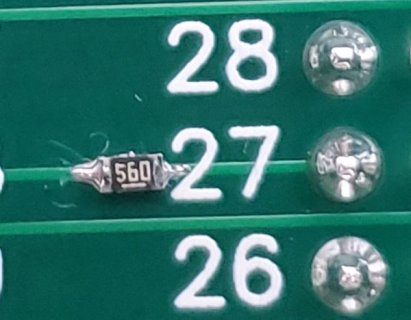
You need to cut out a small section of the trace near the Teensy pin. Don't just try to cut a line across the trace, but instead cut out a section about half the length of the resistor that you will install. Next scrape some of the solder resist off the trace on either side of the cut to expose the copper. Tin the bare copper with some solder and flux or use solder paste. Then use a small SMD resistor like an 0603 to bridge the gap and solder it in place. This pic shows that kind of resistor mod using a 56 ohm resistor. You could also probably use a leaded resistor by soldering one lead to the Teensy pin to hold it firmly in place and then laying the other lead over the tinned cut trace on the other side of the cut and soldering in place.


SPI Series Resistor Modification.jpg
 
Back
Top